Improving Minone and PolyMap with Log-Odds
I have recently upgraded Minone and the PolyMap mapping system, focusing particularly on enhancing our use of a Single Ultrasonic Sensor. While the sensor hardware remains unchanged, introducing the concept of "log-odds" has significantly reduced the impact of noise and false readings, making our maps clearer and more accurate.
What are Log-Odds? (Explained Simply)
Imagine you're guessing whether it will rain today. You might say there's a 50/50 chance—that's "even odds." Now, suppose new clouds roll in, and your chances become "likely" rain, maybe 75%. Each time you get new information, your confidence about rain happening or not happening changes.
Log-odds is just a special way of keeping track of these changing guesses. It turns probability—the chance something is true—into a number that's easier to update quickly. Positive log-odds numbers mean "more likely," negative log-odds numbers mean "less likely," and zero means completely uncertain.
 |
| Occupancy Grids - Binary vs Log-Odds |
Applying Log-Odds in PolyMap's Occupancy Grids
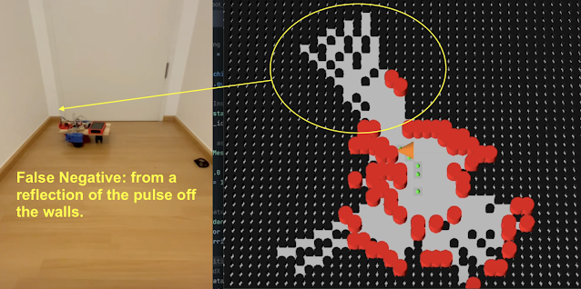
In mapping, especially with sensors like the ultrasonic sensor used in Minone, each measurement tells us something about whether space is empty or occupied. However, sensors aren't perfect; sometimes they say there's something there when there isn't (false positive) or fail to detect something that really is there (false negative).
Using log-odds, The system doesn't just accept each measurement blindly. Instead, it builds confidence over multiple readings. Every time the ultrasonic sensor scans an area:
-
A positive reading increases the log-odds, suggesting the area might be occupied.
-
A negative reading decreases the log-odds, suggesting the area is likely empty.
Over time, genuine obstacles build a strong positive score, clearly marking them as occupied on our map. Meanwhile, random noise, causing occasional false readings, doesn't build enough consistent evidence, so these points eventually fade away, staying neutral or negative.
This approach makes the PolyMap occupancy grids more reliable and accurate, greatly improving how robots navigate and interact with their surroundings.
A Deeper Look into the Math of Log-Odds
Log-odds translate probabilities from their natural scale (0 to 1) into a 'logarithmic space,' which makes it easier and computationally more efficient to combine multiple pieces of evidence. In probability space, values close to 0 or 1 become increasingly difficult to update because small incremental changes can have disproportionate effects. By shifting to log-space, updating becomes straightforward additions and subtractions, maintaining precision across multiple sensor updates.

When updating log-odds:
-
Positive evidence: If our sensor indicates an obstacle, we add a fixed positive log-odds increment, quickly shifting the belief towards occupied.
-
Negative evidence: If the sensor suggests no obstacle, we subtract a smaller fixed increment, slowly shifting back towards uncertainty or free space.
To prevent numerical instability, clamps are applied to the log-odds values. These clamps set upper and lower bounds, ensuring values remain within practical limits, preventing overruns that could result in overly confident (extreme) occupancy or vacancy assertions.
This additive and controlled adjustment property allows for quick, stable, and efficient updating, even with multiple sensor readings, greatly enhancing computational efficiency and clarity in interpreting sensor data.
Practical Results from PolyMap
Since implementing log-odds in PolyMap, there are substantial improvements:
-
Reduction of False Negatives: Previously, true obstacles were sometimes overlooked due to sensor noise and rapid changes in sensor readings. By quickly reinforcing log-odds with positive detections and slowly decreasing with negative readings, our system now reliably maintains the presence of real obstacles, significantly reducing false negatives.
-
Clearer Obstacle Identification: True obstacles are now distinctly recognized after several confirmations, making navigation decisions safer and more confident.
These practical outcomes directly enhance robot efficiency, reducing navigation errors and improving path planning capabilities.
Future Improvements and Considerations
Moving forward, I will be exploring additional enhancements to further refine occupancy grid accuracy:
A key challenge is tackling the ultrasonic sensor's tendency to miss obstacles when pulses reflect at oblique angles, effectively making these obstacles invisible. This issue arises because the sensor’s sound pulse can deflect away, failing to return the echo needed for detection. To address this, I am considering several options:
-
Sensor Fusion: Integrating data from multiple sensor types, such as infrared, alongside our ultrasonic sensor to build an even more accurate picture.
-
Multi-Angle Sensors: Using multiple ultrasonic sensors at different angles to ensure obstacles are detected from various perspectives.
-
Adaptive Orientation: Dynamically adjusting the sensor's orientation or positioning to better capture reflections from challenging angles.
-
Enhanced Signal Processing: Implementing advanced signal analysis techniques to better distinguish weak echoes or indirect reflections.
I believe these improvements will further strengthen PolyMap's reliability, making the robot even smarter and more autonomous.