Showing posts with label ESP32. Show all posts

Wednesday, June 24, 2026

The Ferret - Tunnel Exploring Robot (#1)

TNERA - The Ferret Robot - AI Concept Art

Introduction

I always had a dream in the back of my head about having a robot to go into tiny spaces that I could not. To go down the proverbial rabbit hole and see what is there. This is my goal, to build exploring robots. Even ones that could be recast as pipe-inspection robots. 

Sounded to me like it would be a good weekend project, it also sounded like a good 'new' project that I could test out the capabiltities of using the current AI tools to help build the components. It would be a good test to see how they have improved in the last year. 

So, down the rabbit hole we go! Chasing the AI white rabbit!

Like it or not, We are living in a moment in time in which AI has created a time of software abundance. It is now far easier for individuals to create complex new software with ease. There’s a growing claim, a belief, that "Now anyone, can build anything". Many software Makers are doing just that: they are going back to previous projects that were to onerous to build in the past, and now building them.  

Can this be true for robotics projects as well?

Robotics has always been one of those domains that resists simplification. It is a heavy concentration of software, firmware, electronics, and mechanical design, all interacting in ways that tend to create complexity instead of removing it. Historically, that complexity has been a barrier for automated tools, it also makes it fantastically more interestings.

So this project—The Ferret—is my attempt to explore whether modern AI tools can meaningfully compress that complexity.

The Idea: A Burrow-Exploring Robot

Abandoned Burrow Hole - to be explored

I’ve had this idea for years: a small robot that can crawl into spaces people can’t—burrows, holes, confined environments—and explore them remotely.

To do this, I need something narrow. Cylindrical. Tracked.

A robot that can push forward into an unknown space with a camera and light, acting as a remote presence where a human simply can’t go.

The Core Challenge: Does current AI help here?

Any robotics project sits at the intersection of three domains:

  • Firmware - software that runs on the device
  • Electronics - how components are wired and powered
  • Mechanical design - what the robot physically exists as

AI is clearly strong in firmware and all software development. This part has already become trivial with early 2026 LLMs. Write a good prompt on what you want the firmware to do, and the AI agents can write it for you in minutes.

But how can AI be used to Generate usable 3D printable CAD? used to help design mechanical systems? or provide meaningful assistance with circuitry? This is the real test.

Starting Mechanical Design

The process started not in CAD, but in conversation. Before building anything, I worked with an AI session to:

  1. Define constraints 
  2. Explore design options 
  3. Clarify tradeoffs 
  4. Generate prompts that would later drive development

This turned out to be a useful pattern: design through dialogue first, implementation second.

OpenSCAD and the Nose Cone

I use OpenSCAD for CAD work. It is openSource, and completely codified, which makes it easy for an LLM to write the design in.

Historically, AI has been… really bad at it. Almost unusable.

So I started manually, designing the front of the robot—a nose cone. I knew what I wanted geometrically, but not what to call it. So I asked Gemini Flash. It identified the shape as an elongated ellipsoid, common in aerodynamic designs, and even generated OpenSCAD code for it.  I pasted it in.

It worked immediately.

That was the first signal that something had changed.

Building the Tracks

With that success, I quickly moved over to the design of the caterpillar tracks. This wasn’t my first time building tracked systems (see the Wild Weasel). I had a good mental model of how it should work.  The AI suggested I use Linked track system, where there are two distinct parts like a bicycle chain or chain on a chainsaw. There is some benefit of the cog locking of that method. However, I would prefer a universal (continuous) track system based on preference and past experience. The continuous track uses a single universal track tread that is much easier to print in mass.

The Ferret Robot - Single Track Piece CAD design

The Ferret Robot - Track Pieces in line CAD design

I spent about an hour designing the first track segment manually. It worked well.  a base tread, with a hinge that I could insert small metal rods into. Then, I asked GPT to generate a similar design based on my comments. The initial CAD code output was not very useful. However, I uploaded my design as a rough guide not fully spec'd out, and the AI was able to match and complete the track accurately. The AI was not perfect 'from scratch' like the nose cone, but it was highly effective when guided. 

The Hard Part: Sprockets

Honestly, tracks are easy compared to sprockets. Sprockets are like gears, but they pull chains or track treads instead of meshing with other gears. The geometry of a sprocket is very different to a gear. To work correctly, sprockets require: precise tooth geometry, correct spacing, proper engagement with the track, provide alignment, and support tolerances. Designing a working sprocket is tedious and error-prone.  Another good test of the AI!

The Ferret Robot - Sprocket CAD design

From above, I input the track design to GPT and provided a vague prompt to design a sprocket to fit the track. It did it in less than a minute. The AI generated the geometry, selected a tooth count, and calculated spacing and the included offsets. The design looked impressive, I added an axel and printed it to test.

Again, I found that the design didn’t work perfectly the first time—but it was close. It is not untypical in sprocket design to iterate through small variations to get the right fit and tolerances. This time, instead of manually editing the openSCAD code, I simply described the problem in plain language and let the AI adjust the design. It took five iterations to get a perfect fit. The only parameter I had to tune was offset, which is exactly what you’d expect in manual iteration anyway.

The Ferret Robot - Sprocket sizing iterations. Final on Right
Tensioner and frame on top with sprocket
Track tread length on bottom 

The key difference: I never had to reason about sprocket geometry directly. The sprocket design was custom, not a library. the AI built the hub and teeth on its own. That’s a new skilled behavior to me, the AI has come a long way!

Initial mechanical design assessment

At this stage, I was pretty happy. The Nose Cone was pretty easy to "generate", the track design went better than expected. It took me signifcantly less interations to perfect (and it printed very nicely too). most of that design came from the Wild Weasel, the AI quickly parameterized it. And finally the sprocket was trivial, next to the typical effort to design and adjust. AI can now participate meaningfully in mechanical design—especially when guided. 

Ferret Robot: Original motor idea
pre-V1: nose cone, ESP32-CAM, tracks, sprocket, battery, and motor driver.

So, I was feeling pretty happy. Happily building and happily ignoring some of the more obvious warnings I was getting feedback on from the AI... That is the next story!

Monday, May 5, 2025

PolyMap & MinOne - MinOne gets Log-Odds (#5)

Improving Minone and PolyMap with Log-Odds

I have recently upgraded Minone and the PolyMap mapping system, focusing particularly on enhancing our use of a Single Ultrasonic Sensor. While the sensor hardware remains unchanged, introducing the concept of "log-odds" has significantly reduced the impact of noise and false readings, making our maps clearer and more accurate.

What are Log-Odds? (Explained Simply)

Imagine you're guessing whether it will rain today. You might say there's a 50/50 chance—that's "even odds." Now, suppose new clouds roll in, and your chances become "likely" rain, maybe 75%. Each time you get new information, your confidence about rain happening or not happening changes.

Log-odds is just a special way of keeping track of these changing guesses. It turns probability—the chance something is true—into a number that's easier to update quickly. Positive log-odds numbers mean "more likely," negative log-odds numbers mean "less likely," and zero means completely uncertain.

Occupancy Grids - Binary vs Log-Odds

Applying Log-Odds in PolyMap's Occupancy Grids

In mapping, especially with sensors like the ultrasonic sensor used in Minone, each measurement tells us something about whether space is empty or occupied. However, sensors aren't perfect; sometimes they say there's something there when there isn't (false positive) or fail to detect something that really is there (false negative).

Using log-odds, The system doesn't just accept each measurement blindly. Instead, it builds confidence over multiple readings. Every time the ultrasonic sensor scans an area:

  • A positive reading increases the log-odds, suggesting the area might be occupied.

  • A negative reading decreases the log-odds, suggesting the area is likely empty.

Over time, genuine obstacles build a strong positive score, clearly marking them as occupied on our map. Meanwhile, random noise, causing occasional false readings, doesn't build enough consistent evidence, so these points eventually fade away, staying neutral or negative.

This approach makes the PolyMap occupancy grids more reliable and accurate, greatly improving how robots navigate and interact with their surroundings.

A Deeper Look into the Math of Log-Odds

Log-odds translate probabilities from their natural scale (0 to 1) into a 'logarithmic space,' which makes it easier and computationally more efficient to combine multiple pieces of evidence. In probability space, values close to 0 or 1 become increasingly difficult to update because small incremental changes can have disproportionate effects. By shifting to log-space, updating becomes straightforward additions and subtractions, maintaining precision across multiple sensor updates.

When updating log-odds:

  • Positive evidence: If our sensor indicates an obstacle, we add a fixed positive log-odds increment, quickly shifting the belief towards occupied.

  • Negative evidence: If the sensor suggests no obstacle, we subtract a smaller fixed increment, slowly shifting back towards uncertainty or free space.

To prevent numerical instability, clamps are applied to the log-odds values. These clamps set upper and lower bounds, ensuring values remain within practical limits, preventing overruns that could result in overly confident (extreme) occupancy or vacancy assertions.

This additive and controlled adjustment property allows for quick, stable, and efficient updating, even with multiple sensor readings, greatly enhancing computational efficiency and clarity in interpreting sensor data.

Practical Results from PolyMap

Since implementing log-odds in PolyMap, there are substantial improvements:

  • Reduction of False Negatives: Previously, true obstacles were sometimes overlooked due to sensor noise and rapid changes in sensor readings. By quickly reinforcing log-odds with positive detections and slowly decreasing with negative readings, our system now reliably maintains the presence of real obstacles, significantly reducing false negatives.

  • Clearer Obstacle Identification: True obstacles are now distinctly recognized after several confirmations, making navigation decisions safer and more confident.

These practical outcomes directly enhance robot efficiency, reducing navigation errors and improving path planning capabilities.

Future Improvements and Considerations

Moving forward, I will be exploring additional enhancements to further refine occupancy grid accuracy:

A key challenge is tackling the ultrasonic sensor's tendency to miss obstacles when pulses reflect at oblique angles, effectively making these obstacles invisible. This issue arises because the sensor’s sound pulse can deflect away, failing to return the echo needed for detection. To address this, I am considering several options:

  • Sensor Fusion: Integrating data from multiple sensor types, such as infrared, alongside our ultrasonic sensor to build an even more accurate picture.

  • Multi-Angle Sensors: Using multiple ultrasonic sensors at different angles to ensure obstacles are detected from various perspectives.

  • Adaptive Orientation: Dynamically adjusting the sensor's orientation or positioning to better capture reflections from challenging angles.

  • Enhanced Signal Processing: Implementing advanced signal analysis techniques to better distinguish weak echoes or indirect reflections.

I believe these improvements will further strengthen PolyMap's reliability, making the robot even smarter and more autonomous. 

Sunday, April 27, 2025

PolyMap & Minone: First Test Results (#4)

Simple SLAM Robot: Initial Tests with PolyMap and Minone

Both the PolyMap mapping platform and the Minone robot have reached a level of functionality sufficient for their initial tests together. The early results are exciting, though clearly revealing room for improvement—exactly as anticipated!

Here's a video capturing these very first tests. Having this visual documentation will greatly help us track the robot's progression as we refine and improve the SLAM capabilities.

Overview of the First SLAM Tests

These initial tests show how well the mapping system, PolyMap, works together with Minone, a very minimal robot platform that is built around an ESP32 microcontroller. Minone, equipped with only a single ultrasonic sensor, navigated a confined hallway environment. All communication between the robot and the mapping software was successfully managed via MQTT, demonstrating effective real-time integration.

Minone, alone in the hallway.


In this test setup, Minone was in a hallway out of my vision. My phone was recording its movement. I sat in an adjacent room behind the door and was instructing the robot through the visualization. Commands were sent using MQTT to the robot and telemetry and map data was returned as previously discussed. In this test, I did have the reassurance that it was working, as I could hear the motor movement down the hallway.

Mapping Process and Key Observations

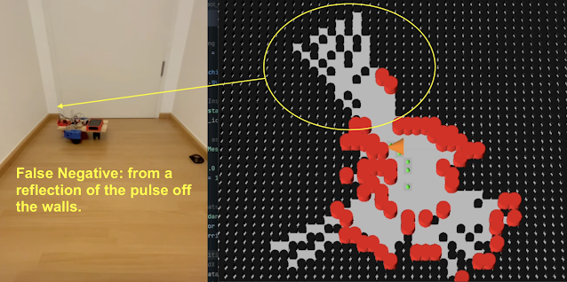
The PolyMap visualization provided live feedback during the tests with telemetry and maps. On the map you can see:

  • Robot position was clearly indicated in orange.

  • Obstacles detected by the ultrasonic sensor appeared in red.

  • Unexplored areas remained marked in black.

  • Telemetry shows the Pose (X, Y, Θ) and state: Manual

PolyMap Viz April 2025 (Totally Not Evil Robot Army)

The visualization effectively demonstrated the system's ability to build a cohesive map from successive sensor readings. However, the tests quickly highlighted significant limitations associated with relying on a single ultrasonic sensor:

  • False negatives: The sensor occasionally failed to detect obstacles, particularly when encountering oblique angles. The pulsed ultrasonic signal reflects off the surface and does not return to the sensor, the device times out waiting, and returns a long distance (in this case greater than 170cm)

  • False positives: There were numerous instances of the sensor incorrectly registering obstacles due to noise and sensor inaccuracies. This could be due to echos, but otherwise indeterminate (for me at this time).

Minone, False Neg due to Reflection in corner.

These limitations underscore a common challenge when using ultrasonic distance sensors. In simple SLAM test, there were no special filter applied or sensor data management used. This is a clear direction for improvement in the next code iteration.

Initial Conclusions and Immediate Next Steps

The primary next step is addressing the significant number of false positive and negative readings produced by the ultrasonic sensor. To tackle this challenge, the mapping algorithm will transition from a basic binary representation (occupied/free) to a probabilistic occupancy grid, employing the log-odds methodology. This approach should significantly reduce the influence of sensor inaccuracies by statistically weighting sensor readings over time.

Looking Ahead: Introducing Mintwo and Exploring Swarms

Future development plans include building an upgraded version of Minone: the Mintwo robot (?!?). This iteration will be enhanced by incorporating multiple IR time-of-flight sensors, dramatically enriching the data quality and robustness. The improved sensory capability of Mintwo will not only enhance individual robot performance but also lay the foundational work for exploring coordinated behaviors and swarm robotics, leveraging PolyMap’s scalable and distributed architecture.

Stay tuned as we continue to iterate and enhance both the PolyMap platform and our expanding army, ehr.. family of robots!

Sunday, April 13, 2025

Minone – Getting the MV#Robot to Stable (#3)

Minone – Getting the MV#Robot to Stable (#3)

It's been a busy stretch since the last update! Many improvements, refactoring, debugging, and learning sessions have pushed the Minone MV#Robot toward a more stable and robust platform.

Code: Structure and States

Most of the recent effort has been dedicated to fleshing out software needed for remote operation. The robot's codebase has significantly expanded, particularly around the command structure. I've implemented a state model to handle essential high-level states:

  • Standby: Robot awaits commands—especially useful after a reboot, allowing manual verification before resuming tasks.

  • Manual: Direct control, crucial for immediate testing and remote operations.

  • Autonomous: Fully independent operation. Future enhancements will include advanced exploration strategies, frontier search, and swarm coordination.

  • Pause: Temporary halt; currently, the robot resumes directly into Autonomous mode.

  • Error: Safety state activated by unexpected issues.

High-level state changes are now managed via an MQTT subscriber, enabling remote state-level commands. In Manual mode, the MQTT listener also accepts individual task commands for immediate execution.

To efficiently handle robot actions ("tasks"), I developed wrapper code that allows manual triggering for debugging flexibility. Additionally, during Autonomous mode, the Robot's Agent autonomously generates tasks, utilizing the same task infrastructure.

Precise Movement Challenges

One aspect differentiating a true robot from a toy or simple remote-controlled device is the ability to move precisely. For mapping and SLAM purposes, it is crucial to know exactly where the robot is and its pose. To understand how much a motor has turned, an encoder is used to 'count' the amount of rotation. Minone uses encoders that are built into recycled Roomba wheel modules I am using. Knowing the number of pulses per rotation and wheel dimensions allows precise odometry calculations—determining how far the robot moves or rotates.

Initially, Minone exhibited incorrect odometry during turns. Calculations seemed accurate—asking to move 10cm resulted in software reports of 10cm—but the physical movement was actually 20cm. This discrepancy first appeared in rotation measurements, which were exactly half the physical result. At first, I assumed calculation errors were related to the complexity of the turn calcuation. The wheels are rotating in opposite directions and you must factor in wheelbase dimensions. A quick patch improved turn precision slightly, but the underlying movement issues remained.

Digging deeper revealed encoder pulse counts were half the expected values. Although the very specific 508.5 pulses per rotation was correct, I initially misunderstood that this value included both rising and falling edges of the encoder's square-wave pulse. A small adjustment resolved this completely:

// --- Encoder Setup ---
void setupEncoders() {
  pinMode(LEFT_ENCODER_PIN, INPUT_PULLUP);
  pinMode(RIGHT_ENCODER_PIN, INPUT_PULLUP);
  attachInterrupt(digitalPinToInterrupt(LEFT_ENCODER_PIN), leftEncoderISR, CHANGE);
  attachInterrupt(digitalPinToInterrupt(RIGHT_ENCODER_PIN), rightEncoderISR, CHANGE);
}

Switching the interrupt trigger from 'RISE' to 'CHANGE' allowed counting both edges. Problem solved! Recognizing this resolved earlier incorrect adjustments, making robot turns and movements significantly more accurate—not perfect yet, but sufficient for this prototype stage.

A cautionary note on AI-assisted coding: Unfortunately, my AI coding companion missed this nuance, underscoring the continued need to have some knowledge of what you are working with, both in code and hardware. The AI repeatedly suggested using 'RISE,' which cost significant debugging time. Only through examining code from other experienced developers—a big shout out to Bill at DroneBot Workshop—did I discover the proper approach.

Coordinate Systems & Rotational Model

Choosing a coordinate system for your robot is critical, impacting navigation, mapping, and visualization. Coordinate systems aren't always the simple math we learned in high school (traditional X/Y axes). You must consider the Z-axis for rotation and eventually 3D mapping, plus how your robot’s "frame of reference" relates to mapping standards reference. Surprisingly, industry standards differ significantly from basic Cartesian assumptions.

I selected a right-handed system (X-forward, Y-left, Z-up) for the robot frame, aligning with robotics conventions used in platforms like ROS. Positive yaw indicates counterclockwise (left) rotation, while negative yaw indicates clockwise (right) rotation. Though initially counter-intuitive, maintaining consistency across code and system interfaces is very important.

Downstream, the Map Manager and visualization components must translate these standards, especially when interfacing with game engines like Godot, which often uses a different convention.

Minone 11 APR 2025 - MV#Robot

Hardware Improvements

The prototype hardware has also been improved in this iteration. Adding a level shifter stabilized communication between components with different voltage domains. To safely power the ESP32 independently, I now directly use a clean 5V source from a power bank rather than the L298N's regulator.

Currently, the robot remains on a breadboard— a big messy rats nest of jumper wires. Future builds will transition to a safer proto-board with robust connectors for stability and better cable management, reducing risk of havoc from loose connections.

Demos: Seeing the Progress!

Here are short videos captured during the build process. The first demonstrates basic movement and scanning routines without intelligent decision-making:

The second video shows progress after foundational movements were implemented but before odometry corrections—movements rely on timing rather than accurate angle calculations. Since filming, accuracy has significantly improved!


Thanks for following along! The Minone MV#Robot journey continues—iterate, iterate, iterate!

Saturday, March 29, 2025

Minone - Starting the build (#2)

Early minone - TNERA MVP Robot

Minone Build Log #2: The Grind Begins

Minone is a Minimal Viable Robot, built as a prototype for my development of PolyMap, a multi-agent mapping system. It’s a bare-bones junkyard robot—scrapped components, an ESP32-S, and some basic electronics. And let me tell you—it’s fantastic for learning how the real physical world and the virtual one collide. And boy, does it grind.

Core Components:

  • ESP32-S dev board
  • L298N - motor driver
  • Scraped Roomba Motor Modules (with encoders)
  • HC-SR04 Ultrasonic Sensor
  • MG90 servo
  • and a 12V/5V power bank

Here is a highlevel schematic of how they are connected together:


Everything’s wired up pretty simply—and that’s where the real problems start. 😄

Voltage in and out: 3.3V vs 5V

The ESP32 runs at 3.3V logic, but nearly all my sensors are 5V devices. That means input signals need to be stepped down, which I’ve handled using voltage dividers. No big deal.

The trickier part? Outputs. The PWM signals that drive the servo, trigger the ultrasonic sensor, and control the motor driver are all a bit underpowered at 3.3V. Some devices tolerate this. The L298N? Not so much.

That means it’s time to level shift those outputs. A voltage divider doesn’t cut it here. I’ll be testing a proper level shifter soon to ensure robust 5V signaling.

PWM Resource Conflicts on the ESP32

One of the most valuable lessons so far: PWM timers and channels are limited and easily conflicted.

At first, I had a nice ultrasonic sweep working via the servo—classic radar style. But after I added the motor drivers and encoder logic, the servo went haywire. High-pitched whining, jittering, and eventually… nothing.

What happened?

Turns out, the servo and motor driver were fighting over the same PWM channels. The servo took channel 0 by default. The motor driver was hardcoded to use channels 0 and 1. This conflicted both the frequency (servo at 50Hz, motor at 5kHz) and the timer allocations.

My first fix: reorder the initializations to let the servo grab a channel first. This helped, but wasn’t enough.

The real fix: manually assign a separate timer and channel to the servo. I dedicated timer 1 / channel 2 for the servo just before attaching its pin. That separated its timing cleanly from the motors—and everything started playing nicely again.

It cost me a bit of time, but the lesson was well worth it: don’t assume PWM resources will sort themselves out.

The Mysterious Unbootable EPS32

When shifting to local (robot power), Minone just… refused to boot. No errors, no logs—just silence. After way too much head-scratching, I finally pulled out the multimeter and discovered the culprit: the L298N motor driver was holding GPIO 12 and 15 high on startup. Turns out, those pins are a bit picky—they must be low for the ESP32 to boot.

No amount of code, pull-downs, or wishful thinking could override the voltage being held by the motor driver’s enable pins. The only fix? Move those signals to different GPIOs. I ended up switching to GPIO 19 and 22, and just like that—boot restored.

Sometimes, it’s not a bug—it’s physics.

A note about "Vibe Coding"

Throughout the development of Minone (and PolyMap), I’ve leaned heavily on LLM-based AI to guide the process—something the industry is starting to call Vibe Coding. As many have noted, Vibe Coding is a fast way to build software that might otherwise be just out of reach. And honestly? I recommend it, but not for beginners to coding.  [Update: Vibe Coding now has negative connotations. What I recommend is using it as a tool, not over dependence on it.]

AI has helped me rapidly prototype, implement features, and solve specific technical challenges. But beware—it’s not all smooth sailing.

Where AI shines is in writing clean, functional code based on known patterns. It’s excellent at pulling in details, explaining APIs, and even suggesting optimizations. But it often struggles with the human side of development—especially incremental development, integrating features, and aligning with the developer’s mental model.

A big part of my time is still spent going back through generated code line-by-line, trying to understand what it’s doing and whether it matches what I need it to do.

There are also assumptions—sometimes wrong ones. For example, in my code, the AI assumed the encoders were infrared-based, when in reality they’re Hall effect sensors. It’s up to the developer to catch those mismatches and feed corrections back into the conversation. Once pointed out, the AI adjusts quickly, but it doesn’t ask enough questions up front to avoid such errors.

Another example: determining the number of pulses per revolution from these old Roomba motors. This spec isn’t widely documented, and the AI couldn’t give a definitive answer. I had to dig through old boards and obscure web forums to figure it out.

The takeaway? AI is an incredible tool—but the human still needs vision, intuition, and a working understanding of how systems should behave. We’re closer than ever, but not quite at full autopilot.

Incremental Robot Development: ✅ Turning left 

Here’s a quick one: I connected one of the motors directly to the battery—pure chaos, purely intentional. 😄

Sure, it was just to confirm the motor worked. But from a test-first, incremental development perspective? We can officially check off:

✅ Turning left.

Progress!

State of the Platform

Minone is now stable. The essentials—WiFi, MQTT, sensor reads, sweeps, motor movement, and encoder feedback—are all working together smoothly.

The platform’s ready for the next steps:

  • Fully Integrated into the Godot visualization
  • A much much more curious Robot Agent
  • Mapping the basement hallway - the Testing Goal

Wednesday, February 19, 2025

Minone - Introduction of my MVP Robot for SLAM Exploration

Exploring Robots are cool. Robots that map their surroundings? Even cooler. But there’s a massive difference between slapping together a chassis and motors and actually building a robot that can autonomously explore and create a map of its environment. That’s the problem I’m setting out to tackle with Minone, my MVP (Minimum Viable Prototype) for an exploration-focused robot.

Minone - MVP for SLAM

Why Start Simple?

Most SLAM (Simultaneous Localization and Mapping) discussions dive straight into complex sensor suites—LiDAR, stereo cameras, high-end IMUs—but I’m deliberately taking the opposite approach. Instead of relying on fancy hardware, Minone is built to push the limits of simple sensors, starting with nothing more than an ultrasonic distance sensor (HC-SR04).

Why? Because understanding SLAM at its core—filtering noisy sensor data, estimating position, and reconstructing an environment—is much more valuable than just plugging in a high-end sensor and hoping for magic. I want to see how much useful data I can extract from the bare minimum before moving on to more advanced solutions.

A Scrap Yard Robot

In true MVP fashion, I built Minone from whatever I had lying around:

  • Chassis: The top of an old wine box. (Recycling counts as engineering, right?)
  • Motors: Two Roomba drive motors salvaged from an old unit.
  • Caster Wheel: From a trashed suitcase. (Turns out, old luggage makes for decent robot parts.)

It’s the ultimate scrap yard robot, which makes it easy to modify as I iterate. That’s already proving useful, since I’m starting to regret my choice of a trailing caster wheel—turning is fine, but the bot has a tendency to tip forward. A problem for Future Me to solve.

Electronics & Control

For brains and motion control, I’m using:

  • Microcontroller: ESP-32S
  • Motor Driver: L298N H-Bridge

This will be my first time working with an ESP-32S, so I’m looking forward to seeing how it handles real-time sensor inputs and motor control. The L298N should manage the Roomba motors' voltage needs just fine (in theory, at least).

The Underpowered Sensor Challenge

The HC-SR04 ultrasonic sensor is laughably weak for proper SLAM. It’s low-resolution, has a narrow field of view, and struggles with certain surfaces. But that’s exactly why I’m using it—I want to figure out how to make the most of bad data.

If I can extract meaningful spatial information from this absolute potato of a sensor, then adding better sensors later (IR, TOF, LiDAR) will only make the system stronger.

What’s Next?

With the basic hardware in place, the next steps will be:

  1. Getting Minone moving – Setting up basic motor control with the ESP-32S and L298N.
  2. Reading sensor data – Making sure the HC-SR04 is providing usable distance measurements.
  3. Starting simple SLAM tests – Even basic dead reckoning will be a good first step.

As I build and test, I’ll be refining Minone’s design—possibly rethinking that caster wheel before it faceplants one too many times.

Stay tuned for the next update! 🚀

Sunday, August 11, 2024

Mojo5: The End of a Journey (#12)


Every project reaches that pivotal moment when progress halts, and the creative spark seems to fade. For Mojo5, that moment has arrived. This little robot has encountered a significant challenge in the design of its abductors. The servos have developed excessive backlash, compromising its ability to stand and walk effectively.

In an attempt to resolve the issue, I removed the servos and installed a 'static' gear to lock them in place. Unfortunately, this fix didn't fully eliminate the backlash, and the problem persists. Addressing this issue would require a major redesign, far more extensive than initially anticipated.

With a heavy heart, I’ve decided that it’s time to retire Mojo5. But as with all endings, this marks the beginning of something new. Long live Mojo6.

Sunday, April 28, 2024

Mojo5 - Inverse Kinematics in Motion (#9)

I've recently implemented an inverse kinematics (IK) solution to enhance the precision and control of robotic leg movements. Our primary experiment involved programming the leg to execute a simple rectangular movement pattern, with a focus on maintaining accuracy and consistency. Here, I will share some intriguing geometrical observations and challenges we encountered.

Intended Path and Test Setup

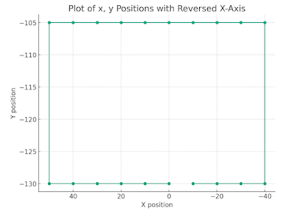
For this test, the robot leg will start in the (0,-130) position. Moving clockwise, It steps backward (in my case more positive, note the inverted x axis) to the (50, -130) position. Next up by 25mm to the top. At this time I use a different z position, but it is hard to see. the motion continues around in a rectangle ending at the start.

Planned path for simple gait test. starting at the center bottom

Video Analysis

In the bolow short video, the robot steps through the gait path. The leg is mounted above the table and horizontal to the table, not in a typical robot position. I have traced each step of the path, with a small dot at the end of the foot.


As seen in the video, the motion lacks the expected precision, influenced by several factors:

  • Fixture Stability: The fixture holding the leg is unstable, contributing to erratic movements.
  • Manual Marking Inaccuracy: Yellow dots indicating key positions were marked by eye, leading to imprecision.
  • Servo Calibration: The calibration of the servo points was approximative. At a setting meant to be 90°, the actual angle could range between 85-95°.

Geometrical Challenges: The Skew Issue

One of the more fascinating issues we observed is the skew to the left when the leg is raised vertically. This skew is likely influenced by the constraints of the 'solution space'—the range within which the actuator operates. As a result, there is a slight warping effect in the grid area over which the leg can move.

Mojo5 Inverse Kinematics - geometric skew

Implications of the Skew

  • Motor-Driven Distortions: The two servomotors, designed to drive the leg in specific rotational angles, do not guarantee a perfectly perpendicular alignment of the movement path. This introduces a mathematical distortion in the intended trajectory.
  • Impact on Gait Creation: While this skew does not necessarily hinder the robot's ability to perform meaningful gaits, it highlights an essential aspect of robotic movement—geometric imperfections inherent in mechanical and software solutions.

Further Research on the Mapped or Solution Space

The space in which the robot can operates can be understood as the geometric area or volume within which the robot can effectively reach and manipulate objects. This space is defined by the following:

  • Reachability: Determined by the length of the robot's arms and the range of motion of its joints. The maximum and minimum extents of each joint define the outer and inner boundaries of this space.
  • Compliance: In the context of SCARA robots, the vertical compliance allows for certain movements in the vertical plane within the workspace. This selective compliance helps in absorbing forces during tasks like assembly, where vertical give is beneficial.
  • Kinematic Constraints: Defined by the robot's mechanical design and the kinematic equations governing its movements. These constraints delineate the paths and patterns the robot can execute.
  • Control Resolution: The precision with which the robot's controllers can position its joints also defines the resolution within the mapped space, influencing how finely the robot can maneuver within its reach.

Certainly a very interesting area of study in robotics!

Monday, April 22, 2024

Mojo5 - My Inverse Kinematics Simplified (#8)

Inverse Kinematics pictured by Dalle3, it can be much simpler!

A much simpler approach

In my previous post on Inverse Kinematics (IK), the complexity might have left some readers puzzled about whether there could be a simpler method to achieve the same results. The good news is, yes, there is a simpler way! Thanks to insights from my roboticist friend Oracid over at the French Robot Forum on Robot Maker, I've streamlined the IK calculations for our Mojo5.

Understanding the Basics

The challenge remains the same: given a target point (x, y), we need to determine the angles of the hip servo (S1) and knee servo (S2). The geometric configuration of the robot's leg has not changed; we still deal with the leg segments L1 (upper) and L2 (lower), equal in length, connected at the knee and forming two sides of a parallelogram.

Geometric Simplification

This parallelogram setup allows us to simplify our calculations considerably. The angle from the horizontal to the leg segment L1 directly provides the angle for S1, and similarly, the angle from the horizontal to the side of L2 gives us S2.

Mojo5 - simplified Inverse Kinematics

Simplified Calculation Steps

Calculate Distance D:  First, we determine the distance from the hip servo to our target (x, y) using the Pythagorean theorem:  D = sqrt(x*x + y*y).  Note D plays a very important role in the following calculations for angles alpha and beta. It is also the line that divides our parallelogram in half.

Calculate alpha:  We will use the trigonometric law of cosines. Given that we know the length of our upper leg L1 and the length of D (aka the hypotenuse), we can calculate the angle between them.  We will call this alpha:  alpha = acos(D / (2*L)).  You may notice this is the same calculation that I used previously. More importantly, this angle alpha is the same on either side of the bisection of the parallelogram by D.

Calculate beta:  We will use a much simpler approach. Also using trigonometry, we see that there is a Right Triangle formed by the Y position, X length and the hypotenuse D. it is possible to calculate this angle opposite of y and D.  beta = asin ( abs(y) / D). It must be adjusted to its reflection in the event that x < 0, this is done (in radians) by subtracting PI from beta. Now one more interesting note. The angle we just calculated is the same angle at top horizontal, this makes it more clear how this beta angle will be used in our final calculations.

Final Servo Calculations:  For S1 we can take the value of beta and subtract apha from it.  Like wise to calculate the angle for S2 and can take the value of beta and add alpha to it to find its value.

  • S1 = beta - alpha
  • S2 = beta + alpha
Hopefully this explaination will help in visualizing the relationships and how to calcuate the correct angles for S1 and S2.  

Here you can view a simplified set of C++ code:

void calcIK(float x, float y, float &s1, float &s2,) {
  float L = 70; //length mm
  float d = sqrt(x*x + y*y);
  float alpha = acos(d / (2*L));
  float beta = asin(abs(y)/d);  if(x<0)beta=(M_PI-beta); 

  s1 = ((beta - alpha) * (180.0 / M_PI));
  s2 = ((beta + alpha) * (180.0 / M_PI));
}


Friday, March 29, 2024

Mojo5 - Video Update, Next IK (#6)

The development of Mojo5 steadily progresses, we've put Mojo5's new leg design through its paces. This latest test, captured in a YouTube Short, showcases a significant enhancement in the design, specifically in the addition of a 'yaw mount'. Although the abduction servo—responsible for the 'yaw' movement—is not operational in this iteration, the primary focus was on the leg's up/down movement capabilities.


One notable improvisation was the use of a hastily clamped mount to a flexible support. This setup was crucial in providing the freedom of movement required while still managing to lift a weight of 370g. It's a testament to our iterative design process, where even makeshift solutions can lead to valuable insights.

On the Horizon: Inverse Kinematics

Moving forward, our journey takes a calculated turn towards the precision of Inverse Kinematics (IK). IK stands at the intersection of design and mathematics, simply translating desired leg positions into specific servo angles. This mathematical approach is the cornerstone for designing diverse robot gaits.

Before we dive into the complex world of gaits, our immediate next steps involve crafting a robust design, delving into the mathematics, coding the solution, and rigorous testing. Stay tuned for our next update, where we'll share our progress in making these calculations a reality for Mojo5.

Saturday, March 23, 2024

Mojo5 - Moving forward in the design (#5)

In our latest chapter of the Mojo5 saga, we're diving deep into the tangible world of robot building, where every breakthrough is hard-won, and every detail counts. This update is all about the real, hands-on progress we've made since last time, focusing on practical challenges and our solutions.

Here's what we've been up to:

Refining the Yaw Axis: We've successfully printed and assembled the new components that accommodate Mojo5's improved yaw movement. This time around, we're talking about the nuts and bolts—literally. Using 30mm M3 screws, to provide the Axis for the Yaw. Now, it is important to consider the build order as the 30mm bolt is added through the servo mount to the yaw frame. The locking nuts and Yaw Gear have to be added before passing through the frame.

Mojo5 - New 3rd Axis added to design

In the photo you can see the original paper sketch, and the 3D printed version. The previous post has the openSCAD version.


Putting Strength to the Test: We didn't stop at design improvements. To really see what Mojo5 can handle, we added a 370g load to its leg. It's essential for us to keep testing the limits and capabilities of our design, especially when it comes to real-world functionality. You can catch this test in action on our YouTube channel https://youtube.com/shorts/EplPBtQ46vw , where we've captured the whole process.


Streamlining the Design: while always on iterating the next improvement, we've started to pare down Mojo5, removing unnecessary parts and integrating a smaller Abductor Servo. This step might seem like we're taking things away, but in reality, we're optimizing for efficiency and performance. Sometimes the best part is the part you leave out - Engineering saying.

Mojo5 - The next iteration, removing un-required structure


Looking Back and Charging Ahead

These updates are more than just progress; they're a testament to the iterative nature of building robots. Each step, whether it's a new screw or a test under load, teaches us something vital about our design and its possibilities.

And as we dive into refining Mojo5 further, removing the extraneous and focusing on what truly matters, we're reminded of the essence of hobby robotics: it's a journey of constant learning, adjusting, and, most importantly, enjoying the process.

We Want to Hear From You

Your thoughts, feedback, and ideas have been incredibly valuable throughout this project. As we continue to navigate the complexities and joys of robot building, we're eager to hear more from you. What challenges have you faced in your projects? How do you approach problem-solving and iteration?

Let's keep the conversation going. Stay tuned for more updates as we push forward, one prototype at a time.

Catch you in the next post!

Sunday, March 3, 2024

Mojo5 - Testing the Leg Design (#3)

Mojo5 Leg Design Test Setup
Mojo5 - Leg Design Test setup

It has been a few months since had some focus on this robot. As a stalled project, it always sits in the back of your head. The next task was to test the configuration to see if this design would be strong enough to lift its own weight in addition to the additional weight of the robot - Chassis, controller, battery, etc.

This weekend, I had a clear desk and I set up the test stand - which failed immediately, snapping my quick clamp with a loud snap. After some time, it occurred to me that I could have the 'chopsticks' extend out in two directions and this would be sufficient to test. Voila!

The robot Leg design with its cam and push rods was easily able to lift 450g + in addition to its own weight. I could not easily strap any additional weight to it. But, I am quite satisfied with this amount of payload for the moment!

Hey - did you notice I am using a Champagne Cork for the foot! :)

Saturday, July 29, 2023

Mojo5 - First concepts and Franken-prototype (#2)

Mojo5: Building a New Robot!

To kick off the design process, the main concept behind Mojo5 was to closely bind the servos together while using an unconventional material – chopsticks(!) – to create a minimalistic chassis.

Initial CAD Drawings:

The journey started with creating initial CAD drawings to visualize the robot's structure and mechanics.

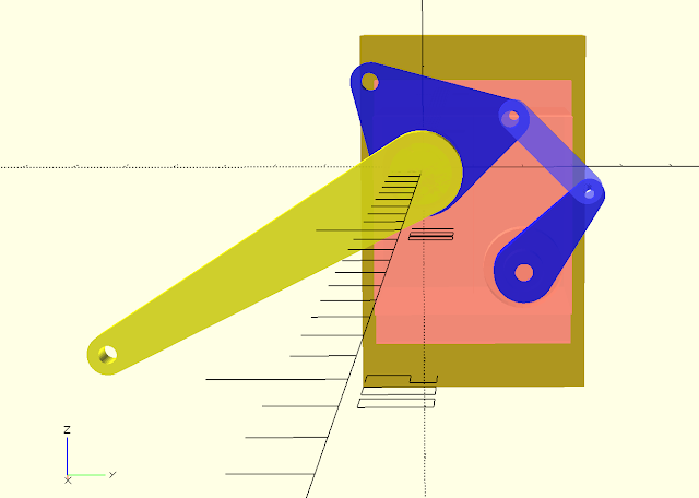
Servo mount is binding the two leg servos together

(Blue) knee servo arm, linkage, and co-axial cam
(Yello) Upper-Leg also co-axial, servo connected

Microcontroller and Servo Driver:

For Mojo5, a major change was adopting the ESP32 controller instead of the simpler Arduino mini-pro used in previous Mojo variants. The ESP32 provides added functionality, including built-in Wi-Fi and Bluetooth connectivity, and ample I/O pins to accommodate future expansions.

Mojo5: ESP32 Micro-controller connected to PCA9586 Servo Driver


To drive the servos, I chose the PCA9685 servo driver, utilizing I2C communications. Although my existing 11kg servos are not the most powerful, the PCA9685 still manages to control them effectively. Furthermore, my familiarity with this driver makes it a suitable choice for use with the ESP32.


The Franken-Prototype:

To quickly test the concept feasibility, an initial prototype was assembled. It consisted of a newly designed 'upper-leg' or 'femur' and a knee-cam sharing the same axis as the upper-leg. Other parts were recycled from earlier robots, giving birth to what we affectionately call a 'franken-prototype'. Franken-prototyping is a common and pragmatic approach to quickly determining the feasibility of an idea.

The first test was crucial – connecting the servos to the PCA9685 and ESP32. I taped the servos together and assembled the required components. Powering the system with a 5V source, I eagerly sought to witness the initial motion and validate the success of this build. And to my delight, it worked! This promising outcome lays a solid foundation for the upcoming design iterations.

Mojo5: Franken-Prototype

In addition to the Prototype, I was able to set up a new repository for the Mojo5 code, and test out the basic set up, communications, and loops.

With Mojo5's initial movements validated, I'm excited to delve deeper into refining and enhancing its capabilities for even greater achievements in the future!