Sunday, November 13, 2022

Robot Runner (#5) - The Difference a Gear Type makes!


After the first prototype testing, it was evident that the 'drive gear' was slipping. This is the gear that is directly connected to the 3D printed gearbox. The gearbox itself may have some backlash (flex), but otherwise the system was pretty tight. It was just that the pressure from the leg mechanism was causing the gear to slip.

Here is a short video of the slippage


The fix to this turned out to be a simple change from a regular spur gear, to a helical gear. (the gear with a slant)

here is the original gear on the gearbox:

robot-runner with original spur gear


and the new CAD model (OpenSCAD)


This gear design has additional surface area touching in the teeth of the gear.  This is all that was needed to improve the operations.

Helical gears are one type of cylindrical gears with slanted tooth trace. Compared to spur gears, they have the larger contact ratio and excel in quietness and less vibration and able to transmit large force. A pair of helical gears has the same helix angle but the helix hand is opposite.  (hkgears.net)

New gear:

robot-runner with helical drive gear


Second prototype test:  Much better


All and all, I will pause this development for the moment. The mechanism is not performing as well as I would hoped for this point in time. I may return to the design. But, for the time, I am thinking more about a more functional base robot - back to MinOne.

Thursday, October 6, 2022

Robot Runner (#4) - two legs running video update

Running Dinobot - by Dalle2 & Doug


Here is the progress on the running robot...

a (literally) short video:


Perhaps I need a little help from another robot to visualize a potential application?  Here are some options from DALLE-2 and Me!  Which do you like?


Running Dinobot - by Dalle2 & Doug

Running Dinobot - by Dalle2 & Doug

Running Dinocyborg - by Dalle2 & Doug


Monday, September 26, 2022

Robot Runner (#3) - Frame and Filling out

 The Runner is getting bigger.  (I really hope this will be able to withstand the weight and keep its balance!)

Robot Runner - OpenSCAD - current build 25-sept-2022

This past week's focus was on building out the frame that will support the running mechanism. The location of the crank gear has to be positioned at a specific distance from the fixed pivot point holding the leg.  More important, these two components must be connected to some frame that the rest of the robot can connect too.  AND! it must support the axel that the drive gears will be attached to.  Therefore, it is a lot ton consider in a single piece. 

My first design was close to working, but the placement of the drive gear axel to the crank gear was too far apart by 1-2mm.  The part was worthless! As part of the re-design, I made the frame and the crank gear stantion (holder) to be seperate pieces. This provides some method of adjustment (with washers) in the cast that it needs to be adjusted.

Video:

Here is a video of the current build 'running' - yes it is running backwards!  

Prototype Running Leg Video

I was able to reuse parts from a pervious robot (mojo4) as a stand in for the gearbox chassis. Had this part been 35mm high instead of 40mm, I could have just used that part.

Now that this is somewhat working, I am returning to the leg structure. I am providing some width to the foot, lower leg, and compliant achilles link.

OpenSCAD - Running Robot Foot Design

and printing in the rain...

3D Printing Robot Parts - in the rain


Saturday, September 17, 2022

Robot Runner (#2) - skinny leg gets thicker

The skinny protype leg needs to be wider to support the robot. In general in needs to be more robust and handle the sideways transitional forces. To do this I am making the leg as wide as the 'pin' in my previously designed hinges. This pin is a 40mm finishing nail, which I have a box of. I have used them has hinge pins in the design of the wild weasel and Mojo4.  This will provide some of the support needed for the sideways forces. The design must be carried forward down to the lower leg and foot.

Robot Running Leg Mechanism -v2

As the width of the robot increases, it is not possible to determine on which side the compliant link will go and the placement of the crank and crank gear. The back lifting linkage, does not need to be 'wide' as it is only projecting the motion, not the support.

Robot Running Leg Mechanism CAD (pins not shown)

Also in this step, I am starting to think of how to drive the crank gear with a motor.  I have a 3D printed gear box from a previous design to reuse (Tilt! and 3D gearbox).  This gearbox will allow the robot to be driven by a brushed motor from a recycled printer.

Here is a video of the current design step:


As you can see, there is a lot of movement generated by the motor. The leg is thrown around creating an oscillation and some unwanted impulse movement.  This will need to be considered (dampened)in future design steps.

Sunday, September 11, 2022

Runner Robot (#1)

I am search of a fast running quadruped (so that I can compete in the Toulouse Robot Races).  I am considering this running mechanism and driving it with a single brushed motor.

This mechanism has worked or others in scholarly papers. I am doing a number of modifications to try to get it to work in a quadruped format.

Robot Runner - Robot leg mechanism

My initial prototype has provided a feasible solution. The mechanism should be able to provide a good profile for walking. I have added some compliancy to provide additional ground contact. From the picutre you can see some of the lengths I have tried for the various linkages. By adjusting these lengths, you can change the step profile.  A profile that has enough rise, and forward movement is desired.

Here is a video of the movements:


The mechanism works well enough in a 2-D plane. This also could have been simulated in programs like Algodoo.  

Next is a tricky issue, the robot will encounter a lot of side loads. Now the mechanism must be designed to reduce the stress of the sideload and transfer (as much as possible) to the chassis of the robot. The image below shows how 'skinny' the "2-D prototype" was.

Side view of the Running mechanism


Follow along to see the progress!

Wednesday, September 7, 2022

In Search of a Stable Robot Leg

This robot leg does not exist. -DALL-E & Doug

I am in search of a "Stable" robot leg.  Stable would mean that it can stand on its own without having to be activity lifted by the motors. In addition, it needs to be able to perform the basic function of lifting and moving in a 3 dimensional 'workspace'.

From a design perspective, lets go over a few requirements:

  • Ability to stand freely supporting its own weight, and preferably some payload
  • Ability to with stand some flexibility, some compliancy
  • Ability to be raised and lowered with in some 'workspace' using up to 3 degrees of freedom (typically 3 servos)
  • Use off the shelf servo motors, springs, 3D printing (PLA), and other common components.

With a stable leg, a biped or quadruped could be realized.


Mojo leg variants:

Here are the iterations of leg designs have I tried so far for the Robot Army.

Leg 1 - Mojo

This was a very primitive first step.  but it has the features of compliance in the two springs.  Obviously it could not support its weight.  This was my first prototype and if you are interested in this kind of stuff - just do it! everyone has a first iteration.

the glass is half full!!
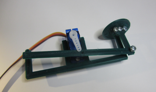

Leg 2 - Mojo2

Mojo2 was a significant improvement in design and lead to a viable walking quadruped. The leg is driven by 2 servo motors. it has a compliant spring to provide stability to stand without motor assistance. The knee was actuated by a servo on the main chases that pulls a cam with a cable to the knee. This cam structure will lift the foot (lower leg) and works against the compression spring providing compliancy.

The issues with this design were centered around the ability for the leg to hold the weight of the robot against the strength to move the leg.  At high duty cycles, the leg would drag along the floor, creating more of a shuffle. Overtime, the cable was prone to stretching, which reduced the performance.  The over all vertical workspace was very limited due to the amount of compression allowed by the spring.

More information can be found on the project pages for Mojo2.

Mojo2 - Quadruped Robot Leg
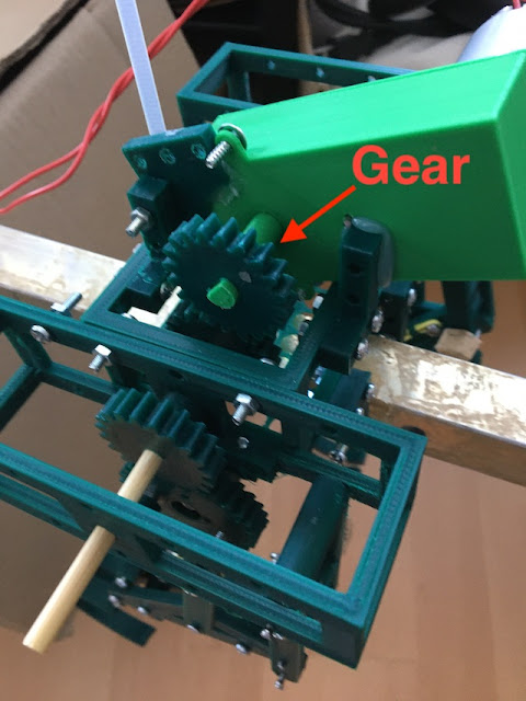
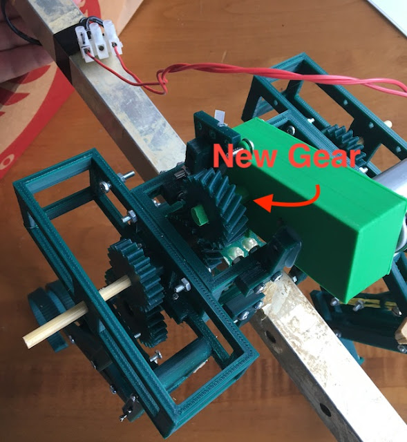
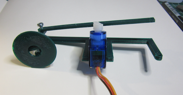
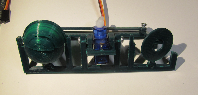
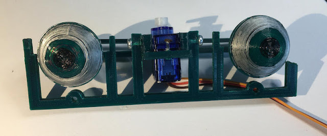
Leg 3 - Mojo3

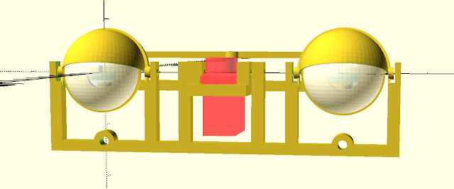
The next design tried to remove design flaws in Mojo2. This design removed the forces being directly applied to the servos by introducing bearings. Servo motors only needed to turn gears, without having the weight of the robot transferred through the servo itself. The gears helped in this regard, but it was not obvious how to create compliancy in the design. 

The design on the left hand was functional, but only provided a very small work space of only 4-6 mm. This video shows the amount of workspace available. The gear pinion on the right design, suffered from gear slippage.

This design also attempted to use 9g servo motors in a very small robot. ultimately, the servos could not provide the performance need to make the robot walk.

Mojo3 - quadruped robot leg designs


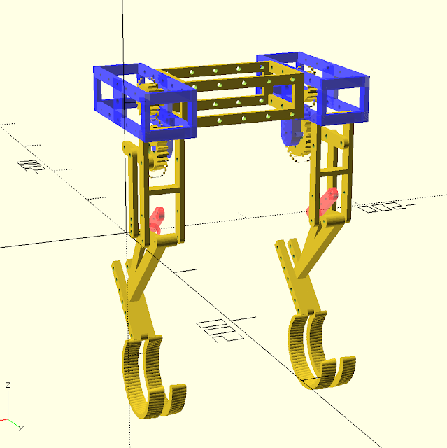
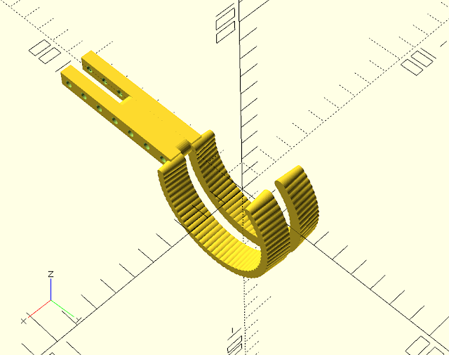
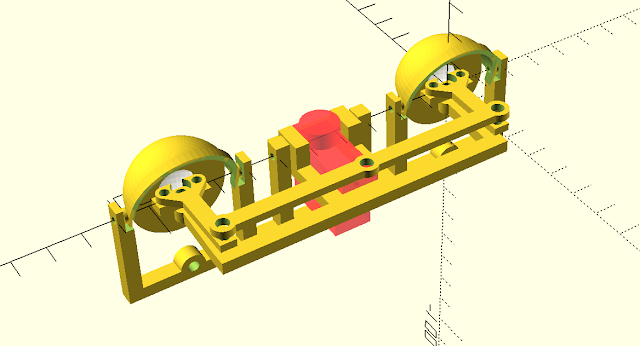
Leg 4 - Mojo4 - the 5 bar design

In a completely new direction, the next design featured 2 servos moving parallel linkages similar to SCARA robot arms. The geometry of the legs was very important to simplify the calculations of the Kinematics. This is the first robot design where I was able to determine and code the kinematics. The workspace in a non-weight-bearing scenario is very large.

Unfortunately ... this design requires the servo motors to activity support the robot. This creates a large power draw which can limit the performance when all servos are firing. Other makers using this design have worked around this issue by introducing elastic bands to keep the leg standing, and reduce the power needed. With an upgrade this leg can be redesigned, it would require elastic (pulling) springs verses compression springs. For the scale of this leg (>20cm) it is has not been easy to source the springs.


Mojo4 - Five-bar style robot leg

New Designs:

Bipedal Legs 

In my research on the internet, I found variations of a bipedal robots that use just 2 servos per leg for the hip and knee joints, with additional compliant linkages for support. The sideways motion provided by a 3rd servo located in front.  This design is by Yuhang Hu, you can see it in action in his Bipedal Robot video.


Yuhang Hu - Bipedeal Design


Disney's researchers took different approach, instead of the Z axis being a single servo, they connected 2 of the leg/knee legs together with a linkage for a single leg. This provided some stability, but doubles the amount of servos to be used.

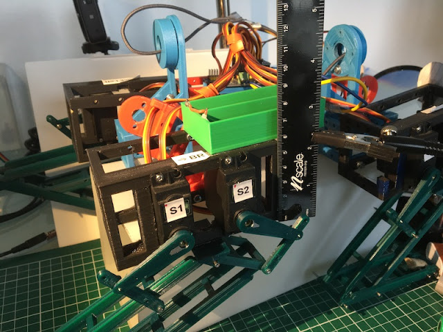
Here is my first cad/print sketches. I have spent my initial development just building the bracket for the servo motor so that it an have rotation from both sides. This view is also hacked together with parts from another robot, just to get a feel for the connection points and where a potential spring(s) would need to be placed.  It was not immediately obvious that this design will fit the criteria.

note:  it looks like a step back in design, but this is just the initial drafting and sizing.  also, the basis for thoughts for this blog entry.

prototype-printed-sketch of a 2 dof robot leg.

While building the above, I also found a potential mechanism that could create a running robot with minimal motors.  Perhaps a mechanism instead with the use of a single brushed motor as the actuator.  

Here is an interesting experiment: Design of biped robot inspired by cats for fast running (by: 
Jongwon Park,Young Kook Kim, Byungho Yoon, Kyung-Soo Kim, Soohyun Kim ) One aspect of using a motor, the rotation will easily provide circular X and Y motion.  The motor is located at O2 and the Hip Joint is statically mounted (to the robot frame).

Design of a Biped Robot

My initial version of this running mechanism.  This is just a printed 'sketch' used to determine sizing and placement of the connectors and screws.  The black bar is a placeholder for a compliant link that will be a tension spring (a spring that is pulled).  the wheel at the top will be driven by a single motor, after some gear reduction. The cam/crank that is attached will need to be short, as in this picture. The distance traveled by this cam has a dramatic impact on the movement of the foot.  the bar at the top, represents the framework that the mechanism is attached to. only the top connection and the wheel is fixed to the frame.

Simple Running Robot Leg Mechanism

Here is a YouTube Short of the the mechanism.


I will be starting a new robot series trying to build a fast running robot with minimal motors. That is the motivation for finding the Stable Robot Leg. The end goal is to create a creature like below, for the Toulouse Robot Race in Nov 2022.  :D

Polecat robot sketch


Monday, June 6, 2022

The Robot Menagerie

It's a great time to be building robots.  Today, there are many robot variants that mimic the biology we see in nature. Here is a collection of a few.  I think this is amazing. At the same time it is fantastic that there are a lot of interesting robots yet to be built, both familiar and alien.  There are no limitations to that which we can imagine. 

Robotic Animals - Bio-inspired Robot Menagerie

The dog

Everyone knows Spot the Boston Dynamics Dog.  There are many many quadruped robots - it is really more of a robotic-question of how to implement the legs. I won't go into any more details here since Quadrupeds are becoming so common to us. Dogs, Cats, Mules, Chetas, etc!  

Original Mojo - Robot Dog design


The interesting thought is how can the envelope of capabilities be expanded, speed, stability, terrain, heights, etc.  Just thinking of what robot videos you have seen, how many have quadrupeds climbing steep rough terrain?

robotic fish

Fish are an interesting twist. There are a few notables.. including this 'spy robot':

Robot - Spy Fish:  Charlie the CIA spy fish.  

The Eel - Eelume Undersea robot for undersea inspection use cases.

Another fish:  BlueSwarm  (IEEE spectrum article)


Robotic Snakes

The Slitherbot:  posted on Hack-a-day Slitherbot

Slitherbot - hackaday.io

TESLA Snake:  This was really a automated Charging Connector prototype. It is best viewed in YouTube at x2 normal speed!


Bionic Menagerie

And then there is Festo!!  Festo is a German company that specialized in automation.  The have a lab that produces bionic innovations which cover a full spectrum of animals.  Anyone (or all of them) of which would be an internet sensation. [makes me wonder why we don't see them more in the wild. ?]

Bionic Swift


Bionic fin Wave - this one is great for swimming in pipes.  Also very similar concept to the motion available for my Millipede project.

Insects:

bionic Ants (Festo) - a natural for swarms too.

Centipede Robot - for getting into hard to reach places


And animal robots are a clear cut winner for pets - more companion animals:

Companion Cats


Animatronics - let's make humans! at least human parts... 

The Eye

this is about the creepiest eye camera there is to date!  It is wonderful! :D


The Claw!

Mark Sen...


and on Tested:


Summary - there are many instances of biomimicry. It is in our very nature to anthropomorphize robots so why not start to build directly in the medium?

There are so many instances of this in our world. this may have to be the first installment. I have waited some time to make this post. It will just need to be an ongoing series.

Tuesday, April 5, 2022

Autonomous Boat: Mayflower

IBM / ProMare - Mayflower 400 ASV

[UPDATE 28.04.2022 - The Mayflower 400 ASV appears to have started a journey across the Atlantic]

IBM and ProMare have teamed up with to create an autonomous boat that is capable of ocean crossing. This, of course, has been already accomplished. This is the next iteration in the development of this technology, and a great way to see how IBM solves this problem

in 2021 the boat attempted to cross from Plymouth, UK to Plymouth, USA. Unfortunately, this attempt had to be aborted due to a mechanical issue (the output exhaust connector failed, which lead to exhaust inside the cabin, eventually affecting the generators efficiency.  stuff happens!).

The boat will attempt the crossing again in the Spring 2022. It is even possible now to connect to the boat to observe the sea-trials. A dashboard has the telemetry from the boat as well as a video feed.

Links


Live view from Mayflower

Video can be found on the Dashboard as well as on IBM's streaming site

ProMare is a not for profit that is "Promoting Marine Research and Exploration". They also have interesting projects such as Ultradeep UAVs and ROVs

[update:  You can find the Mayflower400 ASV at any time using vesselfinder.com]

Thursday, March 17, 2022

Trans-ocean-robots: Autonomous Surface Vehicles


ASV - Autonomous Surface Vehicles  OR 
USV - Uncrewed Surface Vehicles (link goes to Wikipedia)

no matter what you call it... they are the Robots of the Sea! 

It is an excited aspect of robots. Here is some recent news in the realm of marine robotics...

Make Magazine has a nice write up on a group of Makers the had an interest in building a sailing robot to cross the Atlantic Ocean.  Their hopes and dreams lead to projects, hometown support, and eventually - a robotics business. 

Scout - Transatlantic (Make Magazine)

From the article, you see that they have formed a robotics startup in San Diego named Seasats.  seasats (https://seasats.com/)

seasats - X3 robot


good luck to them!  I can add them to my list of other startups in the same space. In fact, It has been about 18 months since my original post on offshore robotics companies.  How are they all doing now?

Ladon Robotics - formerly the Ladon Project, might be getting off the shore again. They recently received a Innovation grant from the NSF for autonomous cargo delivery.  Keep an eye out for updates.


SailDrone - Well, they are a BIG thing now.  have a read of their current mapping HQ.

Ok, this is officially an industry!  These guys SailDrone didn't exist a few years ago. now they have huge contracts with NOAA and the State of Florida.  Their drones are about $500k apeace! 

well that takes us to...

Liquid Robotics (a Boeing Company). They too are growing, and performed a large survey for Japan.

Offshore Sensing - seem to still be making business. Their website has great information, but does not have much upto date on missions.  They do seem to have many international sales offices.  As an example, while in spain, this site came up on their website: Grafinita.

Teledyne Marine - The makers of the most impressive underwater low energy vechiles the Slocum Glider. Now has a page for Teledyne Autonomous Surface Vehicles. It looks like this side of their business is not quite as fully developed (as the slocum) but at least in the Market. Interesting, maybe they are just a little too large for this specific innovation. 

smaller companies like:

Seafloor Systems - Specializing in Hydrographic Survey Solutions

Rest of the World:

so, where are their European counterparts?  who is selling to the UK, Ireland, France, Spain, etc.... (!)  Are the Japanese doing this? what about the south China sea?

Ocean Alpha - Hong Kong

YSI - Hycat

ecomarinepower - has an ASV. They are a Japanese based company.

Norway:

Maritime Robotics - has a number of solutions.  The Mariner (offshore), The Otter (sheltered waters)

In the totally not evil (military) categories...

Utek - from Spain, mostly USV.  And mostly having a big machine gun mounted on a zodiac. Totally, Not Evil...

L3Harris - with the their C-Worker 5 ASV, it is one of a fleet of ASV. Also with great navigation software.

Market:  according to a market analysis report the market players for USV from 2020:  note, most of these are fro Military applications. (Totally Not Evil...)

  • Kongsberg
  • Teledyne Technologies (Teledyne Marine)
  • ECA Group
  • Elbit Systems Ltd.
  • Textron Systems
  • ASV Global - acquired by L3Harris
  • Atlas Elektronik
  • Rafael Advanced Defense Systems
  • Liquid Robotics

of course this is missing the ones mentioned above, such as Sail Drone and Seasats.

And where did Dan McMillon, from my original post the guy that built the robot that naviated from California to Hawaii, and on to New Zealand, endup?  looks like his own (happy) startup. ;) Blue Trail Engineering. Engineering advice and products for Marine Robotics. Way to go Dan!

And for submersibles, this is still super awesome Hydromea.  Ah, swiss innovation... truly robotics leaders in their own rights.  I just wish I had the backing of an institution like ETH Zurich!


That is all for now, stay posted for more updates in the USV / ASV robotics world!

Saturday, February 5, 2022

Design Iterations - Animatronic Eyes


Design Process

Probably the most exciting part of design work is the incremental improvements in each iteration of the design. the enjoyment comes from trying something, testing it, and then finding a new improvement that can be made. (then of course "realizing" this thing you just thought of)

The design iterations of my Animatronic Eyes is a prime example. Currently I am in the middle of this design process where we "Design, Test, Improve, Repeat". I am moving between OpenSCAD, the printer, the assembly and testing, improvements ideas, and Repeat.

Anamatroic Eyes - Early Prototyping (Back)

Animatronic Eyes - Early Prototyping (Front)

The Early prototype supports most of the ideas of the bigger vision.  The eyes will independently move horizontally (left and right) and vertically (up and down). This will require two servos. In this design the eyes will be held in place by a frame that can (eventually) be tilted vertically. The frame will allow the eyes to be fixed, but a moving armature will provide the horizontal movement. This is consistent with many designs on the internet.

This very early prototype is functional, but quickly pointed out that my hole sizes for screws were all too small as well as the frame size. Note: It also clearly shows my minimalist view toward prototypes and products. It does not work correctly, but it works enough to improve the mistake and to start thinking of the next features (the vertical hinge, Eyes, and eyelids)

Back to OpenSCAD

Animatronic Eyes - Prototyping - backside - OpenSCAD

Animatronic Eyes - Prototyping - frontside - OpenSCAD

The next iteration adds primary frame to support the vertical hinge needed to tilt the eyes up and down. This hinge is located centrally and will support the Eye Frame that provides the primary eye support and horizontal servo control. the Frame also Supports for the eyelids. 

This iteration will add the first version of the eyelids. I am starting with the top and a simple hinge method. In some sense all iterations may be 'mixed' between new features like the eyelids and improvements such as full servo mount on the eye support armature.

Printing it out

Design Progression of the Horizontal Armature (version 1, 2, 3)

In this picture you can see the progression of the iterations effect on the design.  The first version on the left is just a simple mock up to see if it size of the armature would be good, and the thickness of the frame. Next support for the horizontal servo was added, and the end holes enlarged. Finally the servo support is strengthened, the end holes are strengthened, and support for the vertical hinge is added. Each iteration helps the next, with the first being pathfinders for the future design.

Current Prototype version - Animatronic Eyes

Finally, here is the current printed version of the prototype. Already it is obvious that the lid will need strengthening. I suspected the frame will need to be divided into parts, as it is difficult to manage the hinge pins in both the vertical hinge and the eyelids.

Animatronic Eyes - early prototyping


Onward and Upward!


Saturday, January 15, 2022

Mojo4 - a little design cleanup (#5)

 Mojo4 has regressed in its ability to shuffle across the floor, unfortunately.  This regression could be due to various causes. I have some concerns over the battery current and the condition of the battery given the temperatures and current. It is also obvious to me that the 'Franken-Prototype' nature is having an impact on the testing of the robot.  It seems that the franken-prototype has taken the design as far as it can go, and an upgrade is necessary to continue forward.  on to --

Mojo4 - Robot is a mess, it needs a better frame or chassis

De-Frankensteining

the majority of the robot is currently built with reused pieces. The is due to the focus being on testing how viable the legs will be for walking.  Having (somewhat) proved this, the next steps need to have a more reliable robot platform.  First on the list is to secure the 4 leg units with a better frame or chassis.  I would like to do this in a way that any new parts, will be used in the future robot (as much as possible).

I will create some Frame Sections that will separate the leg modules, a provide a more stable chassis.  Notice how the right side leg modules are actually not aligned with the rest of the robot - this will certainly have impact to the ability to have a precision walk. 

Backward compatible - should not exist as a design constraint of a NEW robot in the prototype stage! But the question comes to mind.  In order to only build the parts I need, I would need to ensure that the new replacement part fit the same configuration of the existing parts. This mean that the new part is 'backward compatible' with the older part.  This, however, wold be a design sin at this stage. It would limit the innovation of the future robot, tying it needlessly to an obsolete part.  

One note, since my parts tend to have regular 10mm spaced holes for M3 bolts, it does provide a lot of reuse potential.  Unfortunately, i found that my previous designs, I was less concerned with 'standard' parts; therefore many of my old parts do not have regular dimensions (around the rounded cm values). This has limited my ability to reuse.  Going forward I will be more careful to make sure parts I design fit into somewhat regular dimensions.

Frame Section:

I have designed a frame part that will help construct the prototype, while also being a useful part for the future build.  This Frame Section is a box of 10cm x 6cm x 4cm dimensions. It will have M3 holes on the outside and a basic 'floor' for holding components (battery box, or Micro controller).

Frame Section - useful and reusable building component

If I print out 3-4 of these, then I can replace most of the frankenstein-prototype parts used to hold the leg modules in place.  This should provide a more robot platform for testing the basic gait and servo strength.