 |
| The Gardener vs. Slugs! |
I decided to build a Quadruped with only 2 servos (2 degrees of freedom) per leg. These types of robots look anthropomorphically more like Spiders or Bugs rather than Dogs or Cats. So, I will use a working name of "Bug" for this beast!
 |
| From imagination to Sketch - the pantograph leg |
 |
| OpenSCAD image of the Bug Leg with two pivots |
 |
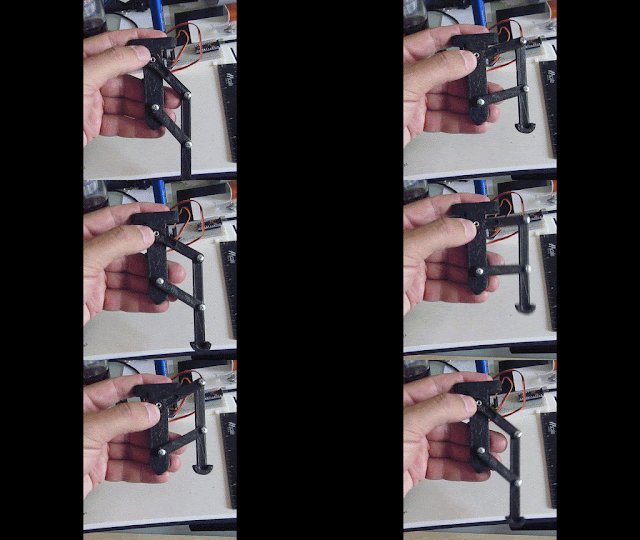
| pantograph leg for the Quadruped |
The design is moved from OpenSCADA to Slic3r to gcode and the 3D printer. Parts are printed and tested. I cycle through a few design iterations this way, to fine tune locations of the servo braces, clearances, and sizing. It is very easy to overlook placements, and having incorrect tolerances.
 |
| Physical prints next to sketched ideas Here the legs are connected with servos and the microcontroller |
The design is checked along the way to make sure each part fits correctly. Having the physical piece is extremely important to the design process. It is hard to realize the small corrections needed from just a CAD program. For instance, the ball pivot of this construct was too small in the 3D printing process to handle the forces of the screw that was used, forcing it causes it to split. This leads to modifications in the design before I print the next set of legs.
 |
| Printed leg connected to controller and battery |
Early tests with the servos, driver, and microcontroller, are essential for validating the mechanism. it is also useful for starting the code base that will be used to control the legs. Once satisfied that 1 leg will work properly, I printed the remaining 3 legs of the Quadruped.
 |
| OpenSCAD drawing of the complete Bug - version 1 |
 |
| Bug Quadruped almost assembled |
From idea to prototype quickly! Most of the design was done on a Sunday morning, while printing was done every few hours during the week.
The next task will be to create a stable walking gait, this is surprisingly non-trivial. I will share that in a future post. Time to get this beasty walking!!
No comments:
Post a Comment