
The parts are sitting on the workshop surface, at least most of them. I thought I had some blockers in the sense that I *thought* I would need to have an encoder to make this work. Now, it occurs to me that the control system doesn't really care how much the wheel has turned, it will be controlling completely on the feedback from the motion sensor! of course!
Finding a good wheel and drive mechanism has been blocking me. This is starting to take some shape in my head/design (at least for the the prototype). I will be using 2, 12-18v brushed DC motors from recycled printers. The motors have a nylon 'pulley' on the spindle that is used to drive a notched belt from the printer. I have found the belts in my pile of parts.(!) The belts solve two problems - 1) I will be able to step down the rotational rate of the motor, and 2) I will be able to directly drive the wheels.
 |
| Tilt - drafting out ideas on paper first -> then to OpenSCAD |
 |
| First attempt to print at m=0.3, the gcode was not precise enough. I reduce the extruded width for external walls to 50% and this helped considerably. |
On to new challenges
I have no wheels that I would like to use for this prototype. given the need for a 3D printed spindle for the belt, it might be best just to custom design and print the wheels as well. Then I can integrate the spindle for the belt, a wheel of good size (10cm diameter) and integrated bearing. From the draft above on paper, I made this concept on OpenSCAD.

The green portion will be the wheel. It has a very wide hub designed to be fitted with a skate bearing. The Yellow portion will be the pulley for the belt. It will be screwed to the side wall of the wheel. The hub of the pulley is slightly smaller than the wheel to lock in the bearing.
3D Printing
Here are the results of the design, printed. It took some test prints to get the resolution correct for the fine detail of the pulley.
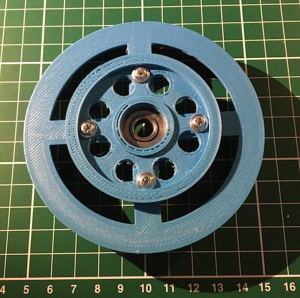 |
| Tilt - 3D printed wheel and pulley for balancing robot |
 |
| Tilt - 3D printed wheel and pulley for balancing robot |
Next Steps:
I am looking now for a piece of metal about 30+ cm long that I can fabricate into the leg of the balancing robot. These recycled printer motors need to have something thin and strong to bolt into. this can be achieved with 3D printing - but I think metal will be a better solution.
Once the leg material can be found, I will be testing the pulley, motor, and tensioning. I have to be careful of any slippage of the belt.
No comments:
Post a Comment