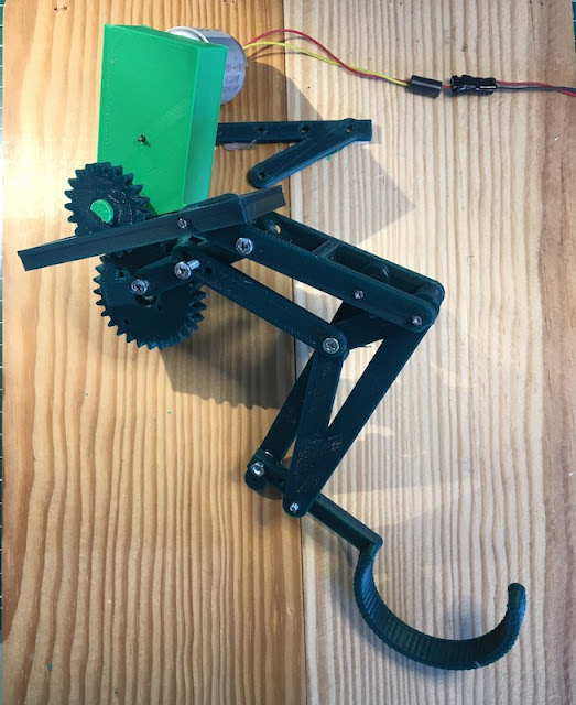
The skinny protype leg needs to be wider to support the robot. In general in needs to be more robust and handle the sideways transitional forces. To do this I am making the leg as wide as the 'pin' in my previously designed hinges. This pin is a 40mm finishing nail, which I have a box of. I have used them has hinge pins in the design of the wild weasel and Mojo4. This will provide some of the support needed for the sideways forces. The design must be carried forward down to the lower leg and foot.
 |
| Robot Running Leg Mechanism -v2 |
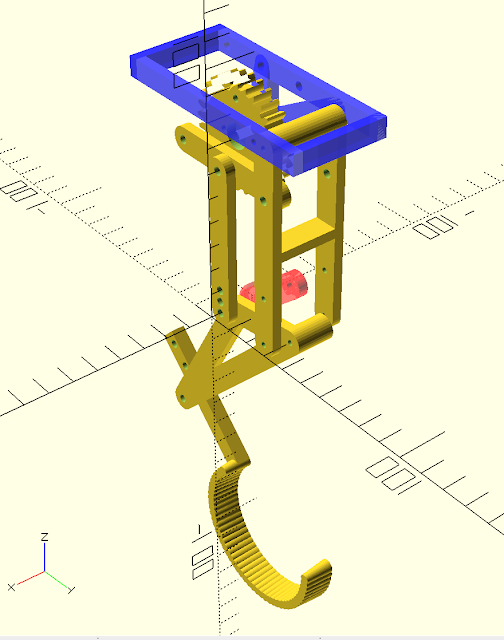
As the width of the robot increases, it is not possible to determine on which side the compliant link will go and the placement of the crank and crank gear. The back lifting linkage, does not need to be 'wide' as it is only projecting the motion, not the support.
 |
| Robot Running Leg Mechanism CAD (pins not shown) |
Also in this step, I am starting to think of how to drive the crank gear with a motor. I have a 3D printed gear box from a previous design to reuse (Tilt! and 3D gearbox). This gearbox will allow the robot to be driven by a brushed motor from a recycled printer.
Here is a video of the current design step:
As you can see, there is a lot of movement generated by the motor. The leg is thrown around creating an oscillation and some unwanted impulse movement. This will need to be considered (dampened)in future design steps.
No comments:
Post a Comment