Wednesday, June 20, 2018

Mojo - A Compliant Quadruped Robot (#6) - Early Tangles

Starting to work on the motion yielded excellent learnings!  :)  But, this is all part of iterating through a design and finding the unknown unknowns.  For a designer, minor setback like this are part of the project, the learning part!  It gets you thinking about what must be changed, and how elements of the design can be improved.


A tangle!

What I learned!

  • The robot currently stands well enough - essentially it is a table!  :)
  • When trying to play with the motion of the legs, the table is naturally unstable => un-table!  which means it falls over easy.
  • I started with basic motion of a single leg.  This was fine, helped tune the bugs out of the Arduino code.  however, since the other legs were not powered, they could not hold their position well.
  • Idea!  Teach the robot how to stand first!  Then we will move on to a lean in one direction and back.
  • The Chassis needed some feature upgrades - so I started the next iteration
    • a cable hook for the servo power - power for the servos comes from a 5V 2.5A phone charger and USB cable.  I cut off the end and use the power and ground to power the PCA9685.
    • The PCA9685 has all the servo connectors going to it. I need to mount it. For this iteration I just screwed it in to one of the empty servo braces.  good for today, but next design will have a mount.
    • The Arduino Mega I am using to prototype with also needs to be on the chassis. right now I have a 'helping hand' hold it.  But the jumpers are a tangle and mixed in with the servo tails.  So, I have added braces and screw mounts for the board. (unfortunately the Mega2650 has really weird screw hole alignment. I will print just a couple of the posts for now.
    • I will have a tether of the servo power and the Arduino connection (to the PC)  for now, but I need to anchor them so they don't jerk the robot around.
    • Also in this build, added the hind leg knee servos.
    • Lengthened the robot, to account for extra spacing needed by the knee cams.
    • Finally, I added a "roll bar" to the top of the bot, 1) protect the boards, 2) to grab when it is falling, 3) because it looks cool.
  • What did not make this iteration:
    • Battery holders for servos and boards
    • button braces for on/off and override button
  • When testing I noticed that I needed to either 1) pull the plug on the servos to get them to relax.  or 2) upload "blink" to stop the Arduino controlling the legs.  This is leading to the need to put the robot into a 'safe mode' when testing.  I figure this can be done two ways
    • add an interrupt to the Arduino code and a subsequent push button to the bot, that will put the code into a 'safe' loop while i reset legs etc.
    • add a simple power switch to the servo motor power line, to disable the servos quickly and safely.
The new frame/body will look like this:

next iteration of the body

On to the printer!!

Latter, after printing...  there is a slight attenuation between the 3D CAD and the printed result.  Not all of the rollbars printed, and the gcode on the braces needs to establish the servo rail before crossing. Raising the brace by 1mm should solve this.  The mounts need to be imbedded more in the brace as well - they came right off with any pressure.  Good notes for the next iteration.

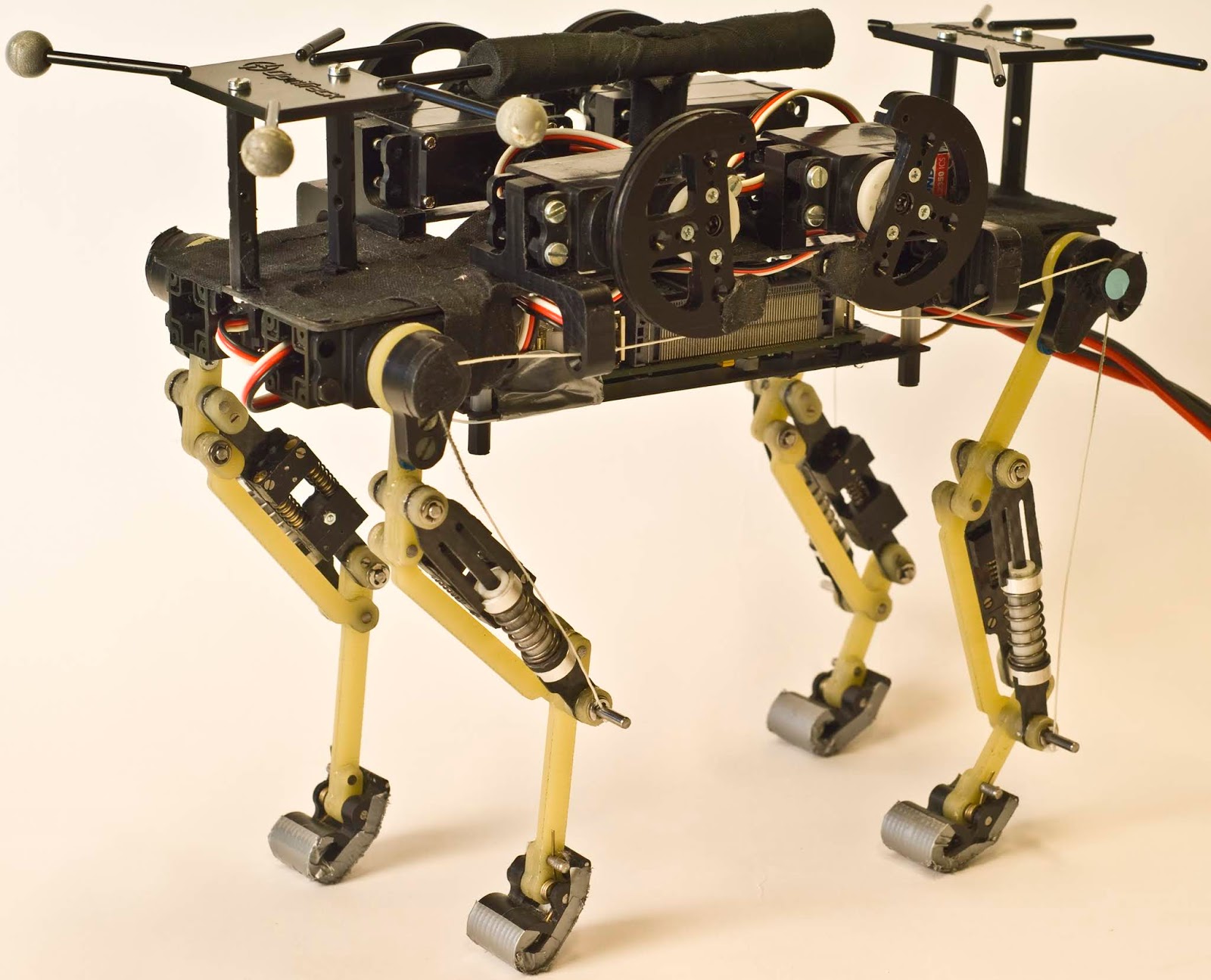
With everything screwed back on, and a power switch thrown in.  Here is the current version of Mojo The Compliant Quadruped Robot!  Good enough to go back to the Kinematics!
Mojo - A Compliant Quadruped Robot

Saturday, June 16, 2018

Mojo - A Compliant Quadruped Robot (#5) - Standing room only

Mojo's leg parts seem to be working well enough.  The legs are light enough to be lifted, which was a concern (see the video).  And the linkages are close to the correct placement.  There is still a lot of revision work needed, But now it was time to put it all together and see how it stands!  :)


And, it stands well (enough!).  All the linkages in the right places it can stand on its own with out falling over - how is that for minimal viable product.

The Chassis here is actually my second draft.  I had not realized my 3D printer would be able to bridge the distances so well.  A friend from the meetup group (thx Rainer!) suggested it would be no problem, and sure enough, it prints very well.  My only surprise in this version was that the algorithm I wrote for printing out the servo posts ended up aligning two in the exact same place. In my rush to print, I didn't realize this until I was counting posts when attaching the servos!  opps!  but, I know that there is an other iteration needed anyway to better space the Cams for the knees and I need a place to put the PCA9685 servo controller and Arduino (not to mention batteries etc.) 

So, even with out all the servos this iteration of the Prototype looks great.  Now I will wire up the arduino again and see how it handles the motion!  

Friday, June 15, 2018

Robots from the Internet

I am starting to see more Compliant Quadruped Robots on the Internet.  Here is the latest I have seen that was inspired by EPFL:


I notice a very different design on the leg for the SEA and back linkage.

Thursday, June 14, 2018

Late Night Robot Hacking

A couple of nights of light night tinkering with the robot yields results!


Grippers!  Every good Robot in the Totally Not Evil Robot Army needs to have a few good sets up Grippers!

and late at night, when it is dark outside and inside the lab...


It starts to move!


Wednesday, June 13, 2018

Learning Robotics

If you are interested in learning more about robotics and finding that YouTube video and blogs are just not as detailed as you desire.  I recommend that you take a look at on-line courses that are available at some of the leading universities.  

The Autonomous Systems Lab at ETH Zürich has courses that are available to be taken on-line.  Some courses are given as an MOOC (Massive Open Online Course).  I have been following along with the Autonomous Mobile Robots - Spring 2018 course.  All of their lecture material is online and free to download.  It is a great introduction in to the engineering that is used to create Autonomous Robots.

It is also a great way to see what the cutting edge at these universities are doing!

Sunday, June 10, 2018

Mojo - A Compliant Quadruped Robot (#4) - Back to the Spring

As it turns out a couple of tries at the "spring" linkage is not working out.  In both cases the chopstick I was using to hold the linkage together was at the same time too long and too short.  Long enough to hold the construction together, is too long for allowing compression. But, short enough for compression results in the piece falling apart. back to the drawing board!

My basic requirements:
  • be able to compress a 25mm spring down to 10mm
  • not capable of pulling apart
  • maintains it's x and y stability (keeps from bending)
  • low friction
  • easy to print
  • easy to construct (minimal glue and clamping)
  • easy to connect to the leg

Taking another close look at the EPFL leg, I see a fork on one side, and rod/piston holding the spring, and a coupling that allow the spring to compress and the piston to slide up.  Sketched out it should look something like this:
EPFL Version top, drawing of new Serial Elastic Actuator bottom


once I go through the CAD it the parts would look like this:

Parts drawn in OpenSCAD


the fork is printed flat, the Piston/post vertical, and the end cap vertical.  As I was designing it, I realized that I need to add the spring to the construction, so the post would have to be separate from the end cap and glued on, once the spring is added.  The ring at the bottom of the post is not physically touching the post - I hope it prints!

I will need to glue the post to the end cap, after the spring is added then glue the fork to the ring.  that is two (three) really big points of failure under stress, so there may be a few more iterations to reduce this risk.


My attempts to build this pointed out a few more flaws.  Conceptually, it should all work together, however the implementation is proving to be problematic - too many glue points where the glue will be the only thing keeping the pieces together.  The resulting engineering is undesirable. It will not be very reliable and will have premature failure.  Back to the drawing board!


This new design has only two parts and no glue!  The design is based on the shock absorbers on my "Hello World" Rover. the two pieces slide together and 'click' into place.  The spring will site between the two.  It should provide the stability and motion needed, although friction will be a problem (especially true since the printing process leave horizontal ridges).  For all the work put into this part this weekend, I think it will do.  :)


After a few iterations on the printer and tweaking the design a bit, I have a working linkage with 7.5mm of compression.  Now, I have to think if my servos can manage this.  Good engineering would have worked out all the forces before hand. But, for this hobby round, I am just tinkering.  The springs are from recycled printers, I have a few to choose from. On the enhanced round I might consider different characteristics such as the amount of travel vs the force.  But, this will do for now - I have 3 more for a complete set.

Learnings this round: a lot of 3D Printing and 3D Part design thinking. Difficulties in getting a high importance but complex part to be built.

next up ...  servos!

Thursday, June 7, 2018

Mojo - A Compliant Quadruped Robot (#3) - Mk3 Leg

I have gone through another design cycle on Mojo the Robot Dog.  This time a quick iteration through the leg design and a new print to test out ideas.  This version is 30% shorter, I am going with 70mm on the leg sections this time.  I trimmed some unneeded weight and bulk on the Tibia. Created a new paw (which I forgot to shorten - so I now have a 'big foot'!).  and to try some ideas around a better compression actuator - which still needs some improvement.

Mojo Leg mk3 w/servo frame

On top you will notice my first sketch at a frame for the robot.  This was a quick sketch to see how things will fit together and get some ideas on how best to scope out the support for servos and controllers.

Many learnings from this iterations - so there will be some design tweaks to come.

  • Screw sizes need refined - Rainer at the Inventors meet up gave me some good ideas on how to tune my 3D printer for this.
  • the Serial Actuator is going to need an overhaul.  This prototype is not working and more resembles a mock up.  It fits, but is not functional.
  • the Frame will need to be wider, longer, and space for the knee actuators and controllers.
  • On the Up side, a bit more practice with the CAD is yielding better results in my builds.  Practice always helps - and you get this only from trying!
With a little more success I am working to have a test with the servos to see if they can lift the legs.  I have thought that these 9gm servos will be too weak for the end result, but good enough to start.

Wednesday, June 6, 2018

Mojo - A Compliant Quadruped Robot (#2) Springs!

For my first set of designs of this walking robot.  I need to design out the compliant leg.  The active part of this compliant robot leg is called a Series-Elastic Actuator.  In layman's terms, I am using springs!  The springs provide the elastic capability for some important functions.  Primarily, it can conserve the energy of actuation - meaning it can store and reuse this force.  It also provides some stabilization when the robot when it bounces.  The trick in the engineering of such a leg will be in determining the right size and strength of the springs.  For this project, my plan is to reuse springs that were harvested from old printers.

here is my first design:

Mojo Leg Mark2


The leg will use two springs, one provide compression (squeezing), the other tension (pulling).  The compression spring appears to be the primary elastic source for walking.  The tension spring seems to just provide stability.

The Tension spring is the simple construction at the back of the "Tarsus".  It is just a small spring and a paperclip in the this prototype.  This was quick to assemble!

The Compression spring has more thought to consider.  The linkage must allow for compression (squeezing), but still maintain the structure of the leg to hold it up.  In this iteration, I printed two "sheaths" that are hollow tubes with the screw holes on the ends. The sheaths are holding a wooden chopstick section and a compression spring.  The length of the chopstick, and the dimension of the leg holds the construction together.  This seems to be sufficent for this test, but will need to be more robust in the next iteration.  And, as yo might notice, the top sheath broke under pressure of the initial tests.

Sheath mk1


For the next iteration:
  • strengthen the compression linkage
  • shorten the leg for testing purposes
  • add mounting holes for servo horn
  • rework the tension spring, move to other side of leg
  • create a more useful paw
  • much much much better linkage connectors!

Sunday, June 3, 2018

Mojo - A Compliant Quadruped Robot (#1) Intro

Every robot geek wants to have a robot dog! or cat!  The idea of having a robot that can run and jump like a house pet is intriguing.  The Use Cases of Search and Rescue, Estate patrol, finding my shoes, and eating weeds in my yard, come to the top of the head.  And a herd of robot dogs would be a key addition to any "Totally Not Evil Robot Army"!  This is my attempt to build one using Maker tech and Urban Mined parts.

Background and Inspiration

The most excellent robotic researchers at the Biorobotics Laboratory (BioRob) have been doing incredible research in quadruped robots.  BioRob is part of the Institute of Bioengineering in the School of Engineering at the École polytechnique fédérale de Lausanne - EPFL.  In 2013, they started publishing their results of their research in dynamic robots using compliant mechanics.  This included the Cheetah Cub - a compliant quadruped robot, the size of a house pet.

Rendered Cheetah Cub - Biorobotics Laboratory, EPFL
The objective of this research is to explore how robotics can benefit from nature in the design and construction of the mechanics.  One quickly realizes that the "static stability" of traditional robots, results in a very clunky design.  For a robot to run and bound, it must have more dynamic properties.  It must also find ways to conserve and use all of the energy produced by mechanics.  This will introduce mechanical compliant systems to create flexibility and elasticity in the robot.  BioRob was very successful in building the Cheetah Cub, and there are some good videos available of it walking, trotting, and bounding.  BioRob has gone on to build a few new variants allowing for steerage, etc.  In order to promote this concept more, it is time for the Makers to get involved and try to replicate the success and evolve the design if possible.

Actual Cheetah Cub - Biorobotics Laboratory, EPFL


Enter the Maker!

My next project was planned to be a Hexapod robot.  But after reading about EPFL - BioRob's success and seeing the OpenCat project, I had enough inspiration to try for the compliant quadruped.  Besides, I am really cheap when it comes to buying parts, a Hexapod requires 6x3 = 18 servos and a quadruped like this would only need 4x2 = 8 servos! (in theory).  And dynamic is way more exciting than static!

A static 3D printed Hexapod leg vs the sketches of a compliant leg.


So, off we go to build Mojo, my compliant quadruped robot dog.  With Sketch pad in hand, I started to draw out what I have seen in the EPFL pictures.  Paper drawings lead to my OpenSCAD design.  Which I created my first draft on the 3D printer.  For Mark1, I can only say that 1) "Do It" is achieved - the project is started and 2) It stands, sort-of, kind-of.  :)

Mojo Leg mk1 - it does stand...
More to come...

Friday, June 1, 2018

Hello World!

"Hello World" is the ubiquitous start to all things technical! It is the classic program that beginners write to understand what the most 'basic' program is. For the maker working with physical computing, "Blinky light" is stated as the "Hello World" equivalent. Now that we have makers by the droves jumping into Robotics and Mechatronics, what would be the bench mark for "Hello World"? Perhaps, it should be the ever popular "RC Car with Camera Rover".

Here is my "Hello World!" in Robotics.  "Polybot" - the Rover:


It is comprised of fairly standard components for this type of build:
  • Chassis of an old RC car. Removed all of the existing controller components. Kept the physical chassis, wheels, struts, drive motor, steering motor, and awesome bumper.
  • Raspberry PI for the brains.  Command, control, communications, video, etc.
  • Off-the-Shelf USB webcam
  • Double H-Bridge for motor control
  • Portable power: 4XAA battery pack for the motors, USB Power bank for the RPI
  • 3D printed frame to attach the RPI, Camera, and stow away the power bank
For hardware, this is a pretty basic set up. It does not get much simpler. One of the challenges for a beginner is how power is managed. In this case, by having a separate power source for the motors, separate from the RPI, solves the issue of having to use a Buck Converter to reduce the voltage for the RPI.

Of course, its the control of the Rover that makes it a Robot vs. a RC car. I used Python as the base language to set up the code to drive my Rover.  Python's control of the GPIO of the PI is simple enough to control the car. The drive software takes a simple command of forward/reverse, left/right/straight combinations. 

To add my own twist to the Polybot Rover, I decided to use MQTT as a protocol to communicate with the Rover and provide it with commands. This would allow me to create different clients that can provide the command signals to the rover.  By nature that would mean that the rover could be controlled by humans - or a massive Totally Not Evil Robot Army Controller, mewha ha ha. But, I digress.


To use MQTT, I created a 'Base Station' that hosted a Mosquito Broker. The Rover's command software is a MQTT Listener written in Python. And I wrote a Flask Web App, that uses Socket IO and MQTT Client to input the commands and publish them to the broker. 

The Flask, Socket IO, and MQTT are all Python libraries and easy to program. The interface used a simple 6 quadrant set of buttons for Left Forward, Forward, Right Forward, Left Reverse, Reverse, and Right Reverse. It also contained an input field to designate the 'distance/time' to be traveling. The MQTT messages were a very simple LF3 - Left Forward Three, command protocol.

One advantage of using Flask for the Web App is that it is immediately viable for use on a mobile device. The device just needs to be on the same Wifi Network as the Rover, and then connect to the Web App.


Web cam streaming, was provided by using FFMPEG to capture video from the camera and pipe it to stdout. This allows for the ability to create a lifestream on YouTube. This streaming ability has a significant lag, but it really cool to see your Rover on YouTube.  Cool, but not quite FPV! :)

The best part of doing a "Hello World" is that is gets you actually started 'doing it'!  Once you get comfortable with the very most basic, then you can start making your really cool ideas become reality.

There are lots of ways to take the Polybot Rover forward.
  • Add better portable power, with more energy for the motors
  • integrated streaming on the Web App
  • Status messages, Sensor feedback
  • Commands, servos, and actuators on the Rover.  Grippers!!
  • Autonomous control, AI
  • make 10k more rovers, and create a Totally Not Evil Robot Army (ma haha)!!
its only limited by imagination! :)