Showing posts with label Servo. Show all posts

Saturday, March 29, 2025

Minone - Starting the build (#2)

Early minone - TNERA MVP Robot

Minone Build Log #2: The Grind Begins

Minone is a Minimal Viable Robot, built as a prototype for my development of PolyMap, a multi-agent mapping system. It’s a bare-bones junkyard robot—scrapped components, an ESP32-S, and some basic electronics. And let me tell you—it’s fantastic for learning how the real physical world and the virtual one collide. And boy, does it grind.

Core Components:

  • ESP32-S dev board
  • L298N - motor driver
  • Scraped Roomba Motor Modules (with encoders)
  • HC-SR04 Ultrasonic Sensor
  • MG90 servo
  • and a 12V/5V power bank

Here is a highlevel schematic of how they are connected together:


Everything’s wired up pretty simply—and that’s where the real problems start. 😄

Voltage in and out: 3.3V vs 5V

The ESP32 runs at 3.3V logic, but nearly all my sensors are 5V devices. That means input signals need to be stepped down, which I’ve handled using voltage dividers. No big deal.

The trickier part? Outputs. The PWM signals that drive the servo, trigger the ultrasonic sensor, and control the motor driver are all a bit underpowered at 3.3V. Some devices tolerate this. The L298N? Not so much.

That means it’s time to level shift those outputs. A voltage divider doesn’t cut it here. I’ll be testing a proper level shifter soon to ensure robust 5V signaling.

PWM Resource Conflicts on the ESP32

One of the most valuable lessons so far: PWM timers and channels are limited and easily conflicted.

At first, I had a nice ultrasonic sweep working via the servo—classic radar style. But after I added the motor drivers and encoder logic, the servo went haywire. High-pitched whining, jittering, and eventually… nothing.

What happened?

Turns out, the servo and motor driver were fighting over the same PWM channels. The servo took channel 0 by default. The motor driver was hardcoded to use channels 0 and 1. This conflicted both the frequency (servo at 50Hz, motor at 5kHz) and the timer allocations.

My first fix: reorder the initializations to let the servo grab a channel first. This helped, but wasn’t enough.

The real fix: manually assign a separate timer and channel to the servo. I dedicated timer 1 / channel 2 for the servo just before attaching its pin. That separated its timing cleanly from the motors—and everything started playing nicely again.

It cost me a bit of time, but the lesson was well worth it: don’t assume PWM resources will sort themselves out.

The Mysterious Unbootable EPS32

When shifting to local (robot power), Minone just… refused to boot. No errors, no logs—just silence. After way too much head-scratching, I finally pulled out the multimeter and discovered the culprit: the L298N motor driver was holding GPIO 12 and 15 high on startup. Turns out, those pins are a bit picky—they must be low for the ESP32 to boot.

No amount of code, pull-downs, or wishful thinking could override the voltage being held by the motor driver’s enable pins. The only fix? Move those signals to different GPIOs. I ended up switching to GPIO 19 and 22, and just like that—boot restored.

Sometimes, it’s not a bug—it’s physics.

A note about "Vibe Coding"

Throughout the development of Minone (and PolyMap), I’ve leaned heavily on LLM-based AI to guide the process—something the industry is starting to call Vibe Coding. As many have noted, Vibe Coding is a fast way to build software that might otherwise be just out of reach. And honestly? I recommend it, but not for beginners to coding.  [Update: Vibe Coding now has negative connotations. What I recommend is using it as a tool, not over dependence on it.]

AI has helped me rapidly prototype, implement features, and solve specific technical challenges. But beware—it’s not all smooth sailing.

Where AI shines is in writing clean, functional code based on known patterns. It’s excellent at pulling in details, explaining APIs, and even suggesting optimizations. But it often struggles with the human side of development—especially incremental development, integrating features, and aligning with the developer’s mental model.

A big part of my time is still spent going back through generated code line-by-line, trying to understand what it’s doing and whether it matches what I need it to do.

There are also assumptions—sometimes wrong ones. For example, in my code, the AI assumed the encoders were infrared-based, when in reality they’re Hall effect sensors. It’s up to the developer to catch those mismatches and feed corrections back into the conversation. Once pointed out, the AI adjusts quickly, but it doesn’t ask enough questions up front to avoid such errors.

Another example: determining the number of pulses per revolution from these old Roomba motors. This spec isn’t widely documented, and the AI couldn’t give a definitive answer. I had to dig through old boards and obscure web forums to figure it out.

The takeaway? AI is an incredible tool—but the human still needs vision, intuition, and a working understanding of how systems should behave. We’re closer than ever, but not quite at full autopilot.

Incremental Robot Development: ✅ Turning left 

Here’s a quick one: I connected one of the motors directly to the battery—pure chaos, purely intentional. 😄

Sure, it was just to confirm the motor worked. But from a test-first, incremental development perspective? We can officially check off:

✅ Turning left.

Progress!

State of the Platform

Minone is now stable. The essentials—WiFi, MQTT, sensor reads, sweeps, motor movement, and encoder feedback—are all working together smoothly.

The platform’s ready for the next steps:

  • Fully Integrated into the Godot visualization
  • A much much more curious Robot Agent
  • Mapping the basement hallway - the Testing Goal

Sunday, June 23, 2024

Mojo5 - Enhancing Performance with More Powerful Batteries (11)


Mojo5 - with power bank battery

Welcome back to the "Totally Not Evil Robot Army" blog. In this 11th installment of the Mojo5 series, we’re going to dive into a crucial aspect of building robust quadruped robots: using more powerful batteries to drive hobby servos. Specifically, we'll explore how increasing the available amperage and voltage can significantly improve the performance of underpowered servos and the considerations needed to ensure safe and efficient operation.

The Problem with Underpowered Servos

Building a quadruped robot like Mojo5 with cheap hobby servos often leads to performance issues. Many of these servos, such as the MG995, are slow and lack the torque needed for dynamic movements. Even with a 5V power supply, these servos can become wobbly and unreliable, especially under load. This is where upgrading to more powerful batteries comes into play.

The Limitations of the Original Power Configuration

Initially, Mojo5 used a 5V 12000mAh power bank. While this power source had a high capacity, it was limited to a maximum output of 3A. Given that the MG995 servos have a stall current rating of up to 3A each, the total current demand for the robot could easily exceed 20A during peak operation. This significant shortfall in available current was a primary cause of the robot's poor performance.

Upgrading the Power Source: LiPo Batteries

Based on previous discussions and experiments, we found that using a more powerful battery can drastically improve servo performance. Upgrading to a LiPo battery with a 2200mAh capacity, 7.4V voltage, and a 50C discharge rating provides the needed boost. This battery can supply well over the 20A needed by the servos, addressing the current limitations of the previous power source.

Considerations for Over-Volting

  1. Risk of Burnout: Exceeding the servo’s voltage rating does carry a risk of burnout. However, anecdotal evidence suggests that slight over-volting is generally safe if monitored properly. Implementing a voltage regulator could limit the current capacity, which might be counterproductive. In general voltage regulators on servo power sources are not recommended.

  2. Separate Circuits for Different Servos: For servos with lower voltage ratings, such as the MG90 (max 6V), consider creating a separate circuit to avoid over-volting. This will add an additional circuit which can be problematic. For my experiments with Mojo5, I used the same circuit.

Practical Application: Experimenting

Initial Setup

  1. Battery Connection: Connect the 7.4V 50C LiPo battery directly to the power bus of the PCA9685 servo driver, bypassing capacitors and regulators. This setup ensures the servos receive power directly.

  2. Handling Large Wires: Safely connecting XT-60 battery connectors and their thick 12 AWG wires to smaller electronics is challenging. Using a bare copper PCB or prototyping PCBs with multiple copper lines can provide a more robust connection. Soldering all wires together is an ugly but space-efficient solution.


Not Recommended!


In this experiment, I took the short cut and soldered the large wires directly in to a dupont connector. The connector was connected directly to the servo bus. This is not a recommended practice! I better connection with larger wires is recommended. In this particular case, as long as all of the servo motors do not stall, then only brief seconds of +20A current would be expected.  Current greater than 7A for sustained periods of time would destroy the connectors.

Experiment Results

After connecting the 7.4V battery:

  • Servo Performance: There was a noticeable improvement in servo actuation. The MG995 servos operated better, with no immediate burnout.
  • Heat Management: Monitoring the temperature of connectors and wires is crucial. Using a finger-test method (keeping fingers on components for one minute) can help identify safe current levels. If components become too hot to touch, reduce the current.

To visualize the improvement, I have embedded a short video showing Mojo5's performance with the original 5V power bank versus the upgraded 7.4V LiPo battery. Notice the difference in servo response time and stability.


Long-Term Solutions

While the initial experiments are promising, long-term solutions require more robust hardware:

  1. Custom Servo Driver Board: Developing a servo driver board with better connectors and thicker traces can handle higher currents more efficiently. This would replace the PCA9685 board, which is not designed for high current loads.
  2. Current Monitoring: Implementing current measurements and safety features like e-fuses can prevent overcurrent situations and protect your components.

Conclusion

Upgrading to more powerful batteries can significantly enhance the performance of underpowered servos in your DIY robots. While there are risks associated with over-volting, careful monitoring and proper hardware can mitigate these risks. As we continue to push the boundaries of DIY robotics, sharing these experiences and solutions will help us all build more capable and reliable robots.

Sunday, May 19, 2024

Mojo5 - Mirrored Servo Control for Opposite Side Legs (#10)

Mojo5 - Two Legs with Symmetric Control

Introduction to Mirrored Servo Control (Symmetric Control)

One of the primary challenges in developing Mojo5 was ensuring synchronized movements between the servos on opposite sides of the robot. To achieve this, we employed a straightforward yet effective approach: mirroring the servo movements by reflecting the target angles.

Technical Implementation

To implement the mirroring effect, we introduced a boolean parameter in our Servo structure to indicate whether a servo should be mirrored. The adjustment is applied directly in the servo control function.

void moveServo(const Servo& servo, int pos) {
  pos = max(servo.minPos, min(pos, servo.maxPos));
  int pulseWidth =  map(pos, servo.minPos, servo.maxPos, servo.minPWM, servo.maxPWM);
  pca9685.setPWM(servo.num, 0, pulseWidth);
    if (servo.mirror) {
        pos = 180 - pos;  // Adjust the position if mirroring is needed
    }
    pos = max(servo.minPos, min(pos, servo.maxPos));
    int pulseWidth =  map(pos, servo.minPos, servo.maxPos, servo.minPWM, servo.maxPWM);
    pca9685.setPWM(servo.num, 0, pulseWidth);
}

the following structure is used to define all the elements of the servo

struct Servo {
  uint8_t num;
  int minPos;
  int maxPos;
  int minPWM;
  int maxPWM;
  int minRange;
  int maxRange;
  int minRangePWM;
  int maxRangePWM;
  bool mirror;  //true => adjust IK if opposite side
};


The results of this code are directly observed in the output for the Pulse Width Modulation (pwm) values that are sent to the servos.  Here you can see the servo values are 'reflected' or 'mirrored', symmetrical to one another:

Mojo5 - Symmetric control - pwm values over a rectangle gait


Practical Application and Results

In our setup, the mirror effect (symmetric control) is particularly useful for maintaining symmetry in the leg movements. This approach simplifies the inverse kinematics (IK) calculations, as the same code can be used for both sides of the robot with the mirrored adjustment applied where necessary only at the servo control.

To illustrate this concept, we've embedded a short video demonstrating the addition of a leg from the opposite side of Mojo5. The IK calculations are identical, but the servo angles are adjusted by reflecting the target angles, resulting in a mirrored motion that maintains the robot's symmetry.


Insights on Mirrored Movements

Creating a mirrored movement (symmetric control) for servos is crucial for several reasons:

  • Symmetry and Balance: Ensuring that both sides of the robot move in a symmetrical manner is essential for maintaining balance, especially in quadruped robots. Asymmetrical movements can lead to instability and erratic behavior.
  • Simplified Coding: By mirroring movements, the same IK code can be reused for both sides, reducing complexity and the potential for errors. This makes the development process more efficient and the codebase easier to maintain. The servo angles are simply adjusted because all servos turn counter-clockwise and have a 0 to 180° range based on their orientation. Servos on the opposite side face differently, so this mirroring adjustment is necessary.
  • Consistent Gait Patterns: Symmetrical leg movements are vital for creating smooth and natural-looking gait patterns. Mirroring helps in achieving uniform step lengths and timings, which are important for the robot's locomotion.

Summary

The mirroring technique (symmetric control) we've implemented in Mojo5 represents a significant simplification in controlling symmetrical movements in quadruped robots. By introducing a boolean flag in the servo structure and adjusting the servo angles accordingly, we achieve mirrored movements without duplicating the IK code. This not only enhances the efficiency of our development process but also ensures more consistent and predictable robotic movements.

Sunday, April 28, 2024

Mojo5 - Inverse Kinematics in Motion (#9)

I've recently implemented an inverse kinematics (IK) solution to enhance the precision and control of robotic leg movements. Our primary experiment involved programming the leg to execute a simple rectangular movement pattern, with a focus on maintaining accuracy and consistency. Here, I will share some intriguing geometrical observations and challenges we encountered.

Intended Path and Test Setup

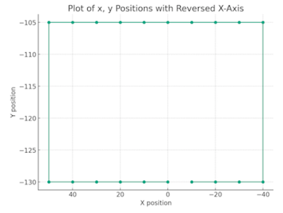
For this test, the robot leg will start in the (0,-130) position. Moving clockwise, It steps backward (in my case more positive, note the inverted x axis) to the (50, -130) position. Next up by 25mm to the top. At this time I use a different z position, but it is hard to see. the motion continues around in a rectangle ending at the start.

Planned path for simple gait test. starting at the center bottom

Video Analysis

In the bolow short video, the robot steps through the gait path. The leg is mounted above the table and horizontal to the table, not in a typical robot position. I have traced each step of the path, with a small dot at the end of the foot.


As seen in the video, the motion lacks the expected precision, influenced by several factors:

  • Fixture Stability: The fixture holding the leg is unstable, contributing to erratic movements.
  • Manual Marking Inaccuracy: Yellow dots indicating key positions were marked by eye, leading to imprecision.
  • Servo Calibration: The calibration of the servo points was approximative. At a setting meant to be 90°, the actual angle could range between 85-95°.

Geometrical Challenges: The Skew Issue

One of the more fascinating issues we observed is the skew to the left when the leg is raised vertically. This skew is likely influenced by the constraints of the 'solution space'—the range within which the actuator operates. As a result, there is a slight warping effect in the grid area over which the leg can move.

Mojo5 Inverse Kinematics - geometric skew

Implications of the Skew

  • Motor-Driven Distortions: The two servomotors, designed to drive the leg in specific rotational angles, do not guarantee a perfectly perpendicular alignment of the movement path. This introduces a mathematical distortion in the intended trajectory.
  • Impact on Gait Creation: While this skew does not necessarily hinder the robot's ability to perform meaningful gaits, it highlights an essential aspect of robotic movement—geometric imperfections inherent in mechanical and software solutions.

Further Research on the Mapped or Solution Space

The space in which the robot can operates can be understood as the geometric area or volume within which the robot can effectively reach and manipulate objects. This space is defined by the following:

  • Reachability: Determined by the length of the robot's arms and the range of motion of its joints. The maximum and minimum extents of each joint define the outer and inner boundaries of this space.
  • Compliance: In the context of SCARA robots, the vertical compliance allows for certain movements in the vertical plane within the workspace. This selective compliance helps in absorbing forces during tasks like assembly, where vertical give is beneficial.
  • Kinematic Constraints: Defined by the robot's mechanical design and the kinematic equations governing its movements. These constraints delineate the paths and patterns the robot can execute.
  • Control Resolution: The precision with which the robot's controllers can position its joints also defines the resolution within the mapped space, influencing how finely the robot can maneuver within its reach.

Certainly a very interesting area of study in robotics!

Monday, April 22, 2024

Mojo5 - My Inverse Kinematics Simplified (#8)

Inverse Kinematics pictured by Dalle3, it can be much simpler!

A much simpler approach

In my previous post on Inverse Kinematics (IK), the complexity might have left some readers puzzled about whether there could be a simpler method to achieve the same results. The good news is, yes, there is a simpler way! Thanks to insights from my roboticist friend Oracid over at the French Robot Forum on Robot Maker, I've streamlined the IK calculations for our Mojo5.

Understanding the Basics

The challenge remains the same: given a target point (x, y), we need to determine the angles of the hip servo (S1) and knee servo (S2). The geometric configuration of the robot's leg has not changed; we still deal with the leg segments L1 (upper) and L2 (lower), equal in length, connected at the knee and forming two sides of a parallelogram.

Geometric Simplification

This parallelogram setup allows us to simplify our calculations considerably. The angle from the horizontal to the leg segment L1 directly provides the angle for S1, and similarly, the angle from the horizontal to the side of L2 gives us S2.

Mojo5 - simplified Inverse Kinematics

Simplified Calculation Steps

Calculate Distance D:  First, we determine the distance from the hip servo to our target (x, y) using the Pythagorean theorem:  D = sqrt(x*x + y*y).  Note D plays a very important role in the following calculations for angles alpha and beta. It is also the line that divides our parallelogram in half.

Calculate alpha:  We will use the trigonometric law of cosines. Given that we know the length of our upper leg L1 and the length of D (aka the hypotenuse), we can calculate the angle between them.  We will call this alpha:  alpha = acos(D / (2*L)).  You may notice this is the same calculation that I used previously. More importantly, this angle alpha is the same on either side of the bisection of the parallelogram by D.

Calculate beta:  We will use a much simpler approach. Also using trigonometry, we see that there is a Right Triangle formed by the Y position, X length and the hypotenuse D. it is possible to calculate this angle opposite of y and D.  beta = asin ( abs(y) / D). It must be adjusted to its reflection in the event that x < 0, this is done (in radians) by subtracting PI from beta. Now one more interesting note. The angle we just calculated is the same angle at top horizontal, this makes it more clear how this beta angle will be used in our final calculations.

Final Servo Calculations:  For S1 we can take the value of beta and subtract apha from it.  Like wise to calculate the angle for S2 and can take the value of beta and add alpha to it to find its value.

  • S1 = beta - alpha
  • S2 = beta + alpha
Hopefully this explaination will help in visualizing the relationships and how to calcuate the correct angles for S1 and S2.  

Here you can view a simplified set of C++ code:

void calcIK(float x, float y, float &s1, float &s2,) {
  float L = 70; //length mm
  float d = sqrt(x*x + y*y);
  float alpha = acos(d / (2*L));
  float beta = asin(abs(y)/d);  if(x<0)beta=(M_PI-beta); 

  s1 = ((beta - alpha) * (180.0 / M_PI));
  s2 = ((beta + alpha) * (180.0 / M_PI));
}


Sunday, March 31, 2024

Mojo5 - Inverse Kinematics (#7)

Inverse Kinematics

At first glance, one might think that Inverse Kinematics (IK) boils down to simple trigonometry. However, determining the appropriate angles is merely scratching the surface. The real challenge lies in considering the physical arrangement of servos, the reference frame, and the constraints tied to both the servo capabilities and their placement. Collectively, these factors embody the essence of Inverse Kinematics.

For  Mojo5, I've chosen to use two MG995 servos, arranged in a stack. One servo is responsible for the 'hip' motion, and the other controls the 'knee.' The crux of IK in this setup is to map a target position within the coordinate plane to specific angles for these servos. To streamline the calculations, I've made a series of strategic design decisions. The lengths of the leg segments, L1 and L2, are set to be equal, each measuring 70mm. The hip servo is positioned as the origin point of our coordinate system. The mechanism for the knee is somewhat intricate, primarily because the servo controlling it is not mounted directly on the leg. Additionally, I've introduced a concept of 'yaw' movement along the z-axis, although, for the time being, our IK calculations will focus solely on movements within the x and y axes.

When it comes to calculating the necessary angles through IK, the approach is to visualize a triangle formed by the leg segments. Given that L1 and L2 are of equal length, this triangle is always isosceles. While this detail may seem minor at first, it becomes crucial when applying the Pythagorean theorem—a^2 = b^2 + c^2—to determine the distance (D) between the endpoints of the leg segments. This distance is key to assessing the feasibility of reaching a given target (x, y) position. To ensure reachability, D must not exceed the sum of the lengths of the two leg segments, or in other words, D <= 2*L.

Calculating the Hip Angle (Theta1)

To determine the hip angle, one must sum two distinct angles. The initial angle is formed between the horizontal axis and the target point (x,y) at the end of line D in our coordinate system. This can be calculated using the ArcTangent function, specifically arctan2(y/x) in standard practices. However, in my application, I employ arctan2(-y/x). The choice to use a negative y value due to my y values will consistently fall below zero. An alternative approach could involve taking the absolute value of the ArcTangent result to ensure a positive angle.

Following this, it's necessary to find the interior angle between line D and leg segment L1 within our conceptualized triangle. This angle, designated as alpha, can be determined through the law of cosines. In a simplified form, the calculation of alpha is expressed as acos(D / (2*L)). By adding alpha to the previously calculated angle, we derive the hip angle. However, there's a twist due to the servo's counterclockwise incrementation: the actual Theta1 is the supplement of the sum of alpha and our initial angle, mathematically expressed as Theta1 = 180 - (alpha + theta).

Mojo5 - Inverse Kinematics of the Hip Joint

Calculating the Knee Angle (Theta2)

To calculate the knee angle, our first step involves identifying the interior angle between the two legs, L1 and L2, which we'll refer to as beta. Once again, the law of cosines proves invaluable for this calculation. While the deeper mathematical proofs are better left to academia, the simplified formula to compute beta is given by acos((2*L^2 - D^2) / (2*L^2)). This equation allows us to calculate beta, which represents the angle between the leg segments in our model.

However, to translate this angle into a form usable by the servo mechanism, additional adjustments are necessary due to the servo being linked to the leg segments via cams. We must take the supplementary angle to beta. This supplementary angle, once processed through the cam system, achieves the effect of pulling the leg segments into the correct position but in a reversed direction. Consequently, we must employ the complement of this supplementary angle to align with the actual geometry and movement direction required by the servo mechanism. This raises an interesting question: could the calculation have been simplified to just beta minus 90 degrees?

Mojo5 - Inverse Kinematics of the Knee Joint


Moving forward

This step concludes the basic framework for the Inverse Kinematics (IK) calculation pertinent to our robotic project. It's important to note that the physical setup of the servos and the joint mechanics imposes certain limitations on movement. Preliminary observations suggest the knee joint is limited to 90 degrees of motion, while the hip joint can achieve approximately 130 degrees. These constraints are not absolute; certain hip positions may permit additional knee movement, although these specific interactions remain to be fully mapped out.

Friday, March 29, 2024

Mojo5 - Video Update, Next IK (#6)

The development of Mojo5 steadily progresses, we've put Mojo5's new leg design through its paces. This latest test, captured in a YouTube Short, showcases a significant enhancement in the design, specifically in the addition of a 'yaw mount'. Although the abduction servo—responsible for the 'yaw' movement—is not operational in this iteration, the primary focus was on the leg's up/down movement capabilities.


One notable improvisation was the use of a hastily clamped mount to a flexible support. This setup was crucial in providing the freedom of movement required while still managing to lift a weight of 370g. It's a testament to our iterative design process, where even makeshift solutions can lead to valuable insights.

On the Horizon: Inverse Kinematics

Moving forward, our journey takes a calculated turn towards the precision of Inverse Kinematics (IK). IK stands at the intersection of design and mathematics, simply translating desired leg positions into specific servo angles. This mathematical approach is the cornerstone for designing diverse robot gaits.

Before we dive into the complex world of gaits, our immediate next steps involve crafting a robust design, delving into the mathematics, coding the solution, and rigorous testing. Stay tuned for our next update, where we'll share our progress in making these calculations a reality for Mojo5.

Tuesday, March 12, 2024

Mojo5 - Rethinking for the Yaw (#4)

Hey everyone! Diving into the heart of our Mojo5 robot project, we’ve hit that exhilarating moment where stepping forward means transforming everything from the ground up. Realizing this early in the prototyping phase? Priceless.

In this fourth installment, we’re rolling out the 'Yaw' – and yes, for our savvy crew following along, that's our latest dive into giving our robot an extra degree of freedom. This isn't just any move; it's what will let our robot's foot pivot with finesse, moving in and out from under the hip, enhancing its agility.

Mojo5 "yaw" mount around servos mount

Our solution? Introducing a lateral axis by creatively engineering a yaw mount that wraps around our existing servo setup. For those of you who’ve been with us, you know the servos and mounts are already pushing our size limits. So, in a stroke of insight, we decided to rotate the entire servo mount by 90 degrees. It’s a straightforward yet revolutionary tweak that cuts through our design challenges, though it does mean we’ve got our work cut out for us updating the OpenSCAD code. But, considering we're still early in the design phase, it's the perfect time for such ambitious changes.

Working in the CAD system really shines here, allowing us to simulate and verify our modifications in real-time. We managed to dial in the yaw movement to achieve +30 and -30 degrees of motion by adjusting just one variable. It’s clear, though, we’re not done iterating; we’ll need to push beyond these angles for the mobility we’re aiming for.

Mojo5: Yaw at +30 degrees

Figure: Yaw at -30 degrees

These figures highlight not just the potential of our design but the iterative nature of robotics itself. While 'Yaw' may be our current terminology, it's the concept and the progress that truly matter.

As we navigate through these updates, your insights and enthusiasm fuel this journey. The path of rapid prototyping is fraught with revisions, but each step brings us closer to realizing the full capabilities of our Mojo5. Stay tuned for the next leap forward!


Note: the correct term for "yaw" would likely be abduction and adduction:

  • Abduction is the movement away from the central axis of the body or, in this case, moving the leg outward from the body's midline.
  • Adduction is the movement towards the body’s central axis or moving the leg inward toward the body's midline.

Sunday, March 3, 2024

Mojo5 - Testing the Leg Design (#3)

Mojo5 Leg Design Test Setup
Mojo5 - Leg Design Test setup

It has been a few months since had some focus on this robot. As a stalled project, it always sits in the back of your head. The next task was to test the configuration to see if this design would be strong enough to lift its own weight in addition to the additional weight of the robot - Chassis, controller, battery, etc.

This weekend, I had a clear desk and I set up the test stand - which failed immediately, snapping my quick clamp with a loud snap. After some time, it occurred to me that I could have the 'chopsticks' extend out in two directions and this would be sufficient to test. Voila!

The robot Leg design with its cam and push rods was easily able to lift 450g + in addition to its own weight. I could not easily strap any additional weight to it. But, I am quite satisfied with this amount of payload for the moment!

Hey - did you notice I am using a Champagne Cork for the foot! :)

Saturday, July 29, 2023

Mojo5 - First concepts and Franken-prototype (#2)

Mojo5: Building a New Robot!

To kick off the design process, the main concept behind Mojo5 was to closely bind the servos together while using an unconventional material – chopsticks(!) – to create a minimalistic chassis.

Initial CAD Drawings:

The journey started with creating initial CAD drawings to visualize the robot's structure and mechanics.

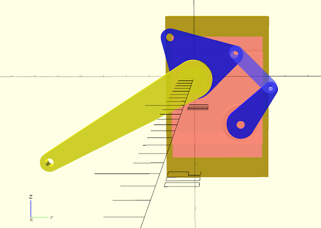
Servo mount is binding the two leg servos together

(Blue) knee servo arm, linkage, and co-axial cam
(Yello) Upper-Leg also co-axial, servo connected

Microcontroller and Servo Driver:

For Mojo5, a major change was adopting the ESP32 controller instead of the simpler Arduino mini-pro used in previous Mojo variants. The ESP32 provides added functionality, including built-in Wi-Fi and Bluetooth connectivity, and ample I/O pins to accommodate future expansions.

Mojo5: ESP32 Micro-controller connected to PCA9586 Servo Driver


To drive the servos, I chose the PCA9685 servo driver, utilizing I2C communications. Although my existing 11kg servos are not the most powerful, the PCA9685 still manages to control them effectively. Furthermore, my familiarity with this driver makes it a suitable choice for use with the ESP32.


The Franken-Prototype:

To quickly test the concept feasibility, an initial prototype was assembled. It consisted of a newly designed 'upper-leg' or 'femur' and a knee-cam sharing the same axis as the upper-leg. Other parts were recycled from earlier robots, giving birth to what we affectionately call a 'franken-prototype'. Franken-prototyping is a common and pragmatic approach to quickly determining the feasibility of an idea.

The first test was crucial – connecting the servos to the PCA9685 and ESP32. I taped the servos together and assembled the required components. Powering the system with a 5V source, I eagerly sought to witness the initial motion and validate the success of this build. And to my delight, it worked! This promising outcome lays a solid foundation for the upcoming design iterations.

Mojo5: Franken-Prototype

In addition to the Prototype, I was able to set up a new repository for the Mojo5 code, and test out the basic set up, communications, and loops.

With Mojo5's initial movements validated, I'm excited to delve deeper into refining and enhancing its capabilities for even greater achievements in the future!

Sunday, July 16, 2023

Mojo5 - Minimal Viable Mojo


Lately, I've been on a bit of a hiatus from robot building, due to the stresses of life and my role as the technical lead in a startup. Yet my thoughts have never strayed from the topic, frequently returning to many different types of robots. But quadrupeds – they have a special place in my heart. You always go back to your first love.

In recent times, there have been numerous discussions about the prerequisites for a good, affordable quadruped. Since embarking on this journey, I've seen a few open-source designs come into existence, such as the Stanford Puppers. To me, the real thrill lies in creating my own, even though I do keep an eye on the work of others in this field.

Looking back, the primary challenges with my previous designs stemmed from the strength of the servos and the overall weight of the robot. To be successful, you need 25+ kg/cm servos with speeds of less than 0.2 seconds for 60 degrees. These servos typically cost $20-25 each (when on sale), and a basic 8-degree-of-freedom quadruped would need eight of them. Before I take the plunge and invest in these high-end servos, I want to try one more design to see if it might be possible to work with the 11 kg/cm servos I currently have.

Enter the Minimal Viable Mojo - Mojo5.

For my Mojo5 design, I aim to strip everything down to the bare minimum necessary to create a walking quadruped.

Minimal parts:

  • 4 leg assemblies
  • 4 quadrant servo mounts
  • 8x MG995 servos (60g each) 480g
  • Light weight wooden dowels connecting the parts
  • Arduino nano pro
  • 7.4v battery for servos
  • 9v battery for controller

This MVM - minimal viable mojo will be a mini-mini quadruped.

Moving forward with this reduced configuration, we have to address several fundamental challenges, the foremost being power optimization. Lighter and less powerful servos mean we have to be extra diligent about weight distribution and energy efficiency.

We're dealing with MG995 servos that are a bit less powerful than the ideal 25+ kg/cm servos, hence the need to maintain a weight that falls within their operating parameters. Every gram of weight matters in our design, hence the decision to use lightweight wooden dowels as linkages.

The Arduino Nano Pro will be the brain of the Mojo5, controlling the servos and coordinating their movement to achieve walking and possible turning. It's a cost-effective and well-documented controller, which makes it ideal for this type of application. However, there will be some limitations due to the lower processing power compared to higher-end controllers.

Power-wise, we're going with a 7.4v battery for the servos and a separate 9v battery for the controller. This dual power source approach is necessary to avoid a brownout scenario when the servos draw a significant amount of current, which could lead to a temporary loss of control.

One innovative aspect of the Mojo5's design will be its cam, pushrod-controlled lower leg. This type of mechanism can provide the torque needed for locomotion without adding much weight, but it does introduce some complexity into the design and programming.

For the leg assemblies, we're starting with 70cm sections. This is a reasonable starting point, but it's likely that we'll have to iterate and adjust these dimensions as we move forward with the project and start testing the prototype. It's going to be a careful balancing act to ensure the legs are long enough for effective locomotion, yet not so long as to place too much strain on our MG995 servos.

Overall, the Mojo5 design will be a journey of continuous iteration and improvement. Each step will likely present new challenges, from structural tweaks to software adjustments, but that's part of the excitement of building our own quadruped from scratch. Stay tuned as we start prototyping and begin to bring Mojo5 to life. We're looking forward to sharing this journey with you.

Saturday, February 5, 2022

Design Iterations - Animatronic Eyes


Design Process

Probably the most exciting part of design work is the incremental improvements in each iteration of the design. the enjoyment comes from trying something, testing it, and then finding a new improvement that can be made. (then of course "realizing" this thing you just thought of)

The design iterations of my Animatronic Eyes is a prime example. Currently I am in the middle of this design process where we "Design, Test, Improve, Repeat". I am moving between OpenSCAD, the printer, the assembly and testing, improvements ideas, and Repeat.

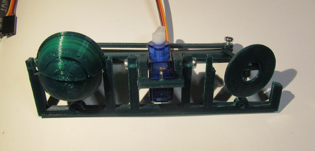
Anamatroic Eyes - Early Prototyping (Back)

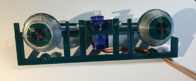
Animatronic Eyes - Early Prototyping (Front)

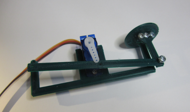
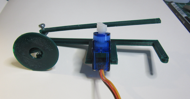
The Early prototype supports most of the ideas of the bigger vision.  The eyes will independently move horizontally (left and right) and vertically (up and down). This will require two servos. In this design the eyes will be held in place by a frame that can (eventually) be tilted vertically. The frame will allow the eyes to be fixed, but a moving armature will provide the horizontal movement. This is consistent with many designs on the internet.

This very early prototype is functional, but quickly pointed out that my hole sizes for screws were all too small as well as the frame size. Note: It also clearly shows my minimalist view toward prototypes and products. It does not work correctly, but it works enough to improve the mistake and to start thinking of the next features (the vertical hinge, Eyes, and eyelids)

Back to OpenSCAD

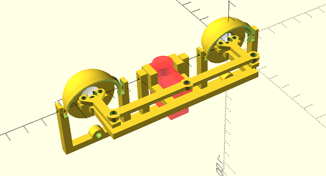
Animatronic Eyes - Prototyping - backside - OpenSCAD

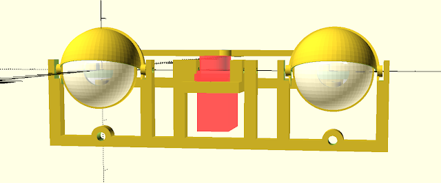
Animatronic Eyes - Prototyping - frontside - OpenSCAD

The next iteration adds primary frame to support the vertical hinge needed to tilt the eyes up and down. This hinge is located centrally and will support the Eye Frame that provides the primary eye support and horizontal servo control. the Frame also Supports for the eyelids. 

This iteration will add the first version of the eyelids. I am starting with the top and a simple hinge method. In some sense all iterations may be 'mixed' between new features like the eyelids and improvements such as full servo mount on the eye support armature.

Printing it out

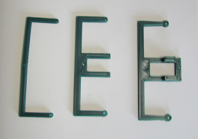
Design Progression of the Horizontal Armature (version 1, 2, 3)

In this picture you can see the progression of the iterations effect on the design.  The first version on the left is just a simple mock up to see if it size of the armature would be good, and the thickness of the frame. Next support for the horizontal servo was added, and the end holes enlarged. Finally the servo support is strengthened, the end holes are strengthened, and support for the vertical hinge is added. Each iteration helps the next, with the first being pathfinders for the future design.

Current Prototype version - Animatronic Eyes

Finally, here is the current printed version of the prototype. Already it is obvious that the lid will need strengthening. I suspected the frame will need to be divided into parts, as it is difficult to manage the hinge pins in both the vertical hinge and the eyelids.

Animatronic Eyes - early prototyping


Onward and Upward!


Saturday, December 18, 2021

Mojo4 - Additional Details (#4)

Here are some more details of Mojo4 - Quadruped Robot Dog

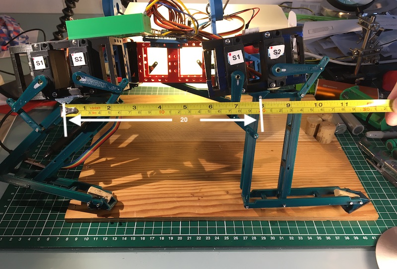
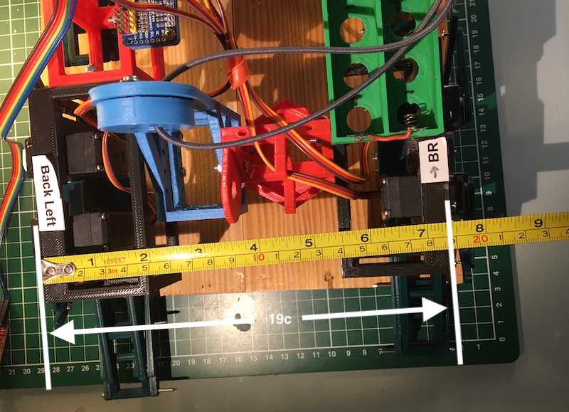
  NOTE:  This is a FRANKENSTEIN Prototype. ;)   it is built mostly with reused 3D printed parts. All of the Dark Green Leg parts were printed so that I could experiment with the 5-Bar design.  Everything else is reused or scrap from previous projects.  This includes the black frames used to mount the servo motors.  My plan is that once this is walking, I will start printing a new chassis with my new-found experiences, also to add the 12DoF.  But first this one must walk.


Here are the pictures:


mojo4-length-18dEC.JPG
Length - measured from the pivot points:


mojo4-width-18dec.JPG
Mojo4 - Width measured on outside legs


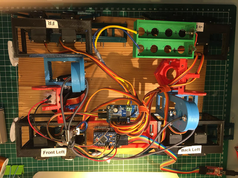
Top - Yes, this collection of PLA is a mess.  

Electronics:  Arduino Pro Mini clone, PCA9685 servo driver, and battery box. 


The 4 servo boxes are on the sides all held together by random parts that fit, bolted together by M3 screws and nuts, some super glue, and hot glue.  Somewhere in there is a 9V battery for the microcontroller, there is a small power switch on the mounting board.


mojo4-top-18Dec.jpeg


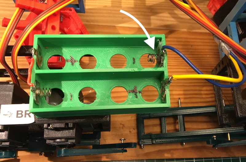
Battery Box:  3D printed, for 2x 18650 batteries. I reused the spring contacts from small toys.  This is a problem since the spring that I have highlighted with an arrow can not handle the current of the batteries and heats up (to the point of melting the hot glue holding it in place).  something else to fix. ;)


mojo4-battery-box.JPG
3D Printed Battery Box for 2x 18650 batteries


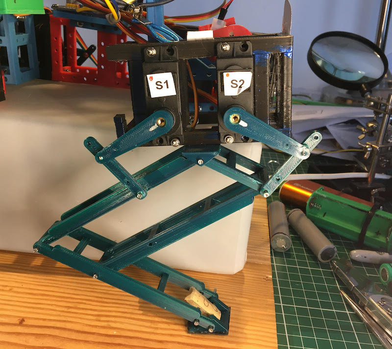
Here is a picture of the leg configuration.  3D printed, minimal material.  It has been strengthen (i made it thicker) to prevent bending. The pivot points are small common nails placed into tubular channels in the leg components. a very cheap easy way of making a hinge. The paw needs a new design.  the current version is 3D printed, has rubber on the bottom, and part of a wine cork to hold it in place.  reuse!  ;)


mojo4-leg-18Dec.jpeg
Mojo4 - 5bar quadruped robot leg