Sunday, December 23, 2018

Robot Arcade - LetsRobot.tv

I am creating a "Robot Arcade" on LetsRobot.tv as a holiday project!  You can visit the site LIVE here:


Robot Arcade - LetsRobot.tv
It is a work in progress, but works well to get all of the robot fantasy out of your head.  I am building this "robot" with mostly parts from recycled printers and some 3D printed parts.  It is using an L298N as the motor controller.  All driven by a Raspberry Pi that is streaming video and controls between it and the LetsRobot.tv servers. I will be using MQTT to pipe commands from the server to various computers controlling the scene.

In the first boot strap days, it was 'challenged' by the 'internet' robot operators.  my motors were not secured and were dancing around the scene.  Actually somewhat fun.  Today I put together this motor mount design and will be using it to build out the Arcade.

3D CAD designed to be a motor mount

I don't quite know what I will do with this yet, but I would like it to be some form of a remote robot - 'game of skill'.  it is fun to see some form of a battle or skill challenge performed by the remote operators.

I am open to suggestions for game ideas!  :)

Monday, December 17, 2018

Centi (#1) - A Bio-Inspired Centipede Robot

Centipede!

I have always wanted to build a Centipede type robot.  It would combine a walking and turning mechanism. And be able to scurry around through obstacles and dreams. Now that I am a self-styled robotist with a 3D printer, I can build one!

DESIGN

Basically, the robot needs to support its weight and payload, be able to move forward/backward, and then steer to the left/right. The target motive force is a single/duo of dc brushed motors, with connectors between the 'segments'. It needs to carry a camera, lights, speakers, for streaming. It needs controller, wifi, RPI(?), and battery / portable power. 

Right now, I am satisfied with it "scurrying" about. But, getting those legs tangled in vertical things will be a future problem. I am not going to worry about that in the first prototypes.

The key to this design will be how to create the basic rotational motion of the leg to Lift-Place-Move each of the legs.  First thoughts had a pair of rotational gears, one to lift the legs, the other to move forward-backward.

Initial thoughts for Leg Motion, placement, and mechanisms
I created a couple of drafts on the cam/lifter/crankshaft thoughts.  But, this seems to be overly complex.  It needed simplicity.

Ball and Socket

The simplest thought would be to have a gear/cam spinning and moving a lever arm of the leg, that is suspended by a ball and socket arrangement. The most immediate concern would be the amount of friction in the ball/socket. This could be managed with some grease. future designs could even use metal or teflon to reduce the friction.  To the CAD!

First draft of the ball/socket - OpenSCAD
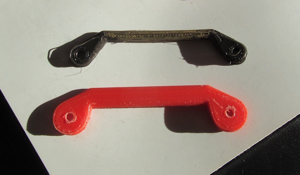
The plan is to 3D print a single full leg segment for testing and Prototyping. I am using a 'chopstick' for the leg.

First print for the prototype - Test, Adjust, and Print again!
The first rough print yielded some immediate feedback. The socket will need to be wider to better contain the ball.  but, sizing on ball for a chopstick style let was right.  I was playing wth an old cam print for sizing, this will go next into the design.  I am also thinking that having a modular/adjustable leg segment will be important.  But, I do not want to get too far ahead in the design there are still a lot of moving variables.

Internet inspiration:
Festo BioFinWave


here are some companies doing somethings with various linkages, but provide a 'fin' that can move on fluid surfaces:


It will be along way for me to go, compared to these systems.

Friday, November 23, 2018

TNERA now Robocasting on Letsrobot.tv

The Totally Not Evil Robot Army is now on LetsRobot.tv

you can now drive one of the robot, or many other enthusiast robots through the robot streaming system.


I have converted the original RC Cart Robot - Polybot, to be on LetsRobot.tv.

Polybot


check out the site (Polybot on LetsRobot.tv) and if the robot is streaming you can control it.

Friday, November 9, 2018

Are Remote Robot Games a 'Thing' yet?

In the past 2-3 years there is a convergence of technologies that are enabling the streaming and control of robots through the internet.  However, remote robotic control, for fun purposes like gaming is still in its infancy.  Why is this?  Why is remote reality gaming and robotic gamings still not a 'thing' (yet)?

The Convergence:
Maker based Robot Creation, Home internet broadband capability, low cost of components, converging with YouTube Streaming, Twitch Game Play, as well as the introduction of chatbots, AI, and ML are converging to make the concept of remote robot games a reality.

I would start to differentiate these as webcams on robots, exploring with robots, and games with robots.  The control of the robot could be observational, or first person.

The most basic - watching robot games on TV, like the picture below. This is very basic robo-sport.  It could be interesting, but in the current state is not very engaging.


I think the real interest in being able to engage with the robot from the internet.  Being able to steer it, perform some action, and potentially meet some (game) objective.

Robospatium
The best example of that in a non-commercial setting would have to be at Homofaciens.de. Homofaciens has build an environment (Robospatium) where you can remotely through the internet connect to a rover-robot and steer it around.  These robots have be working for many years, probably one of, or the first of its kind.  In addition to the robot rover, Homofaciens has a wealth of information for physical computing.  Norbert has a very successful YouTube channel with great videos on building your own robots from everyday items.
R11 Rover - Image from Homofaciens.de
Check it out >> the Original!  In English and German
Homofacian's Robospatium  (https://homofaciens.de/robospatium_en.htm)


Let's Robot.TV - https://letsrobot.tv/

letsrobot.tv is the work of Jillian Ogle. She has been featured on the cover of Make Magazine. She is setting out (like the rest of us) to make robots accessible to everyone, fun and enjoyable.  Letsrobot.tv is a platform where you can view and control remotely robots that are created and 'living' in robocaster's locations. 

There is a heathly community of robot enthusiast developing around Letsrobot.tv. Easy instructions are available how to create and add your own robot to the letsrobot.tv platform. In addition to open source code for the development of the robot, runmyrobot, on Github.


The platform supports a chat function allowing you to participate in the control of the robots with others. Having some of the local tokens, you can steer the robots and have them say things.

There are a few varieties of robots available on the platform.  This would include "The Claw" game, where you can remotely operate a claw arcade game and try to grab prizes from with in.

The letsrobot.tv platform is just gearing up now.  It has received a lot of publicity from MAke and the Makers fair.  It is notable that the platform is handling the video streaming quiet well.  This is one of the more important elements of a remote controlled robot.


Twitch Generation
It seems that the natural platform for the streaming of remotely controlled robots would be Twitch.tv.  Twitch is the streaming platform for electronic games where you can watch professionals and amateurs play video games.  Truly a sign of the times, Twitch itself is the convergence of streaming and gaming communities. To add to this, Twitch has added a creative channel that provides a means for artists and craftsman to stream their creations. So, it would be natural for a robot to stream as well - especially an internet controlled robot.  (Twitch is not alone, YouTube also realizes the value in streaming gaming)


TheOtherLoneStart - Twitch Chat controlled robot battles

One Twitch streamer has recognized this next step and created a Twitch chat controller robot, and associated gaming feature.  If you tune into TheOtherLoneStar twitch streaming channel you may find him building robots, or hosting a battle between his robots.  All for fun, you can certainly internet remote control the bots and have fun with them.  He also has videos of the builds, play action, and a HackaDay project.

Remote Games
Finally there is a new style of remote robotic games that have been created by "Remote Games".  Remote Games is a Ukrainian company that is also "living the dream".  They have created a game that allows for up to 10 (20?) special robot explore and compete an a intricately designed set based on a ghost town near Chernobyl. (yes, the site of the nuclear melt down)


Hyper real set from Remote Games - Image from Remote Games

The hyper-real set is amazing!  Here, with a subscription, you can explore the ghost town with a robot tank and compete in real time with others in different game formats.  The game company is planning to offer franchises of their gaming platform for others to operate their own arenas.  I would liken the model to that of 'laser tag' business plan, but with an Internet audience.

Interesting to note, one of the founder stated "we noticed how quickly remote-controlled game robots are gaining popularity". I think that there view point matches many in the maker/robot community.  we are only just now starting to see the new use cases of robots, robot games, and remotely controlled robots.  

I think it will soon become a 'thing'.


Tuesday, October 30, 2018

Mojo2 (#19) - Walking! A Compliant Quadruped Walking Robot Dog

Mojo2 is walking!  Much tuning and tweaking is needed to make this type of robot walk. The Compliant Quadrupeds do not have the same knowledge and control of robots like Boston Dynamic's Spot mini.  However, like Mojo2, can be significantly smaller, and fast compared to the size and length of the robot.

Check out the video and Totally Not Evil Robot Army Channel on YouTube:


You may have noticed new Cams that are larger and have new features that allow for easier adjustment of the cable tension. This is done by tying the cable to a washer, which can be placed on screws that can be repositioned.

The larger cams have a significant impact on the ability to lift the knee and foot when moving the leg forward. A the gait or walk was slowed slightly, which also created a little more stability.

Did you notice the heavy power bank has been moved to the underside of the robot. This lowers the center of gravity and ... increases stability.  Stability is the common theme.

Most important is the gait. The gait is a true Lateral Sequence Walk. this means that for more than 50% of the time, the feet are on the ground.  But lateral sequence allows for two of the legs to be in motion at the same time.  I feel this is a good achievement for a DYI - 3D printed robot.


Mojo2 - October 30th 2018

Monday, October 15, 2018

Mojo2 (#18) - First Successful Walk

Mojo can now walk!

Numerous testing and enhancements including new feet/"paws", stronger 'tibia', and gait positioning have led to the first successful walk.  See the video below.


Leading up to the successful walk, here are the issues that had to be resolved.


Back side of Mojo2 - right hind leg is translationally forced inward.
The new button - switches between 'walk' and 'stand' is very useful!

New tibia, stronger with larger hinge
one of the biggest issues was the amount of "translational" movement of the leg.  This means that the leg was able to be bent under the robot very easily by the forces put on it. It is caused by the looseness and flexibility in the leg and its joints.  tightening the screws holding the linkages together helps - but increasing the size of the hinges would help more. In addition, creating a tighter screw hole will decrease this flex.  In the process of doing this, it became evident that the 'tibia' linkages were highly flexible - they twisted quite easily. The fastest fix to this issue was to make the tibia thicker and reprint the linkages.

New Tibia - larger, much less torsional flexibility - same size 70mm
With all (8) new tibia installed, the leg structures are significantly more ridged. this prevent the bending inward as seen in the first part of the video.  you can easily spot the new tibia, since they are now red instead of back. 

New Paws with a more compliant capability
The Paws have been replaced in the latest video sequence. you may notice that the robot is resting on the new compliant, spring loaded, paws.  This should add to the compliancy of the robot as well as provide more traction to the pull of the leg.  However, it is evident in later tests, that the compliant paw requires the leg to lift more in order to clear the ground surface.  This is a problem yet to be addressed.


New Distal "paws" or feet, now compliant with effective springs.
Gait Sequence
The gait sequence is actively being adjusted. In the latest runs, the hind legs have been moved back by 10 degrees.  This new posture has improved the stability, and may have been directly responsible for the first successful steps.  However, there are many many variable in this dynamic problem. Tuning one or two often leads to another instability.

In the process of adjusting the tibias, the SEA on the rear hind leg broke. I printed out new one and used a different spring.  The k-constant value of the springs varies by spring. This creates another uncertainty in the tuning of the legs. Having a reliable means to determine the 'k' of the springs would help in creating a consistent behavior across each leg. An adjustable SEA would do wonders.


Broken connector at top of SEA

Getting it to repeat
To be honest, some minor adjustments after the successful test, have created a newly unstable robot. Tightening some of the joints can result in the robot starting to 'moon walk'. This illustraits how sensitive the robot currently is to small changes. More improvements into tuning and adjustment will be needed to start getting consistent results.  But that is what makes this fun.  Right? :)

Another failure: the eye screw suffered metal fatigue being screwed in to a small hole. This can not be removed, thus requiring a new part to be printed.

Saturday, October 13, 2018

New Agility and Application

The Robots are getting better!  They are getting faster and more agile, this will lead to new applications and use cases.  On the 'agile' front new videos are out from Boston Dynamics showing their current Atlas robot doing Parkour!


The dynamics of self-stabilization and location awareness are magnitudes better than just a few years ago when we saw videos of robots stumbling in the woods, gravel, and uneven surfaces.  The magic here is in the controllers that are able to identify the right amounts of force to to apply to surfaces, the right of amount of energy in the actuators, and the enhanced SLAM (Simultaneous localization and mapping)

Can it get more bizarre?  Yes it can!

Meet Salto a small jumping robot from UC Berkeley's Biomimetic Millisystems Lab. Salto is a mono-ped, just one leg. It has inertial stabilization with a swing arm as well as small "quadcopter" motor/blades for pitch and yaw control. Last year we were amazed to see Salto jumping and exploring.  This year, they have had dramatic improvements to the controller enabling more precise hopping to obtain an objective like climbing on a table.


The exploring robots are coming.  They are sprinting, hopping, and learning.

Another good example of the enhancements in SLAM (remember: Simultaneous localization and mapping?) is the MicroMouse challenge.  In this challenge small robotic "mice" are programmed to autonomously search a maze to find the "cheese".  After the exploration phase, the mouse returns to home and runs the maze for speed.  Here is an example of the ability to localize, map, and solve - then make a speed run!


These advancements are increabley in couraging. Access to open technologies, microcontrollers, low cost sensors and actuators, etc, are creating a new revolution in robotics. This will create more abilities, new use cases, and new applications. Remote Exploration is a great new use case.  We have been sending probes and robots into space for some time, with new interest and ability in robotics we will be able to explore much further and in much more detail.  A great example of this is the recent MASCOT and  Hayabusa2 exploration of the Ryugu asteroid. This is fantastic robotic exploration work by JAXA and DLR the Japanese and German space agencies.

There is a whole new domain emerging for robots  ... and the Totally Not Evil Robot Army, is getting ready for it!

Mojo2 - 12 Oct 2018 - A Compliant Quadruped Walking Robot Dog


Wednesday, October 10, 2018

Mojo2 (#17) - Walking Trials Continue

The walking trials of Mojo 2.0 are continuing...

It was evident that the lack of balance of the robot was due to the starting leg positions being too far back, creating a tilt forward from the lack of support for the center of gravity.  This could be addressed by changing the starting angles forward.  


Stability could also be increase by elongating the robot.  Luckily, the mojo2 design provides for just that capability. A spacer of 35 mm was added to the waist of the robot.


New "longer" Mojo2


with the new longer version, it was possible to start it walking.  During the trials, the robot fell over on it's side and broke a "hip".  This part was known to be an issue as it was printed with a clogged 3D printer nozzle.  Luckily, it only required 45 min to print a new hip, and about 15 min to replace it.


Broken Hip

once back together the gait examination continued...  it became clear that Mojo2 was walking backwards - because it was programmed too!  :0

The coding has be reworked and the servos reconfigured.  Mojo is soon to be walking forward, I will have video in the near future. paw stability is now the biggest issue.  more to come!


Mojo 2.0 - A Compliant Quadruped Walking Robot "Dog"

Wednesday, October 3, 2018

Mojo2 (#16) - First Tests Walking Backwards!

If walking backwards was the goal...  Success!!  :)

A busy day working on the robot!  All the parts are printed and assembled.  Now it is in the tuning, adjustments, and fixes.  and TESTING!
Mojo2 - parts in place
 and wired up with servo driver, battery, and Arduino mini pro - microcontroller


Mojo2 - wired and ready to test
Testing was another story. obvious tuning needed. The cables still coming off of the cam, although more reliable than before.  Stability an issue, but it walks!  -- just backward!!


Part of the mystery around why Mojo2 is walking backwards would have to do with the balance of the robot.  In the below picture you can see the positions of the 4 "paws" and legs in comparison to the frame of the robot.  Clearly, the support are well behind the center of gravity.  Thus the need for my hand to provide additional tipping support.
Paw positions indicate balance issues

This may be combined with the gait itself, that is very quick to move the legs to the forward position. This quick motion seems to be have a greater effect on the over all motion vs. the regular step that is at 1/2 of the speed.  It would also be important to consider the amount of ground contact by the feet.

Saturday, September 29, 2018

Mojo2 (#15) - Leg CAD Design and Actual Testing

Mojo 2 is a compliant quadruped walking robot dog - in the making.

Currently, I am testing and making improvements to the design of the Leg Modules. The video below shows the progress of the second iteration of the leg design. The biggest improvement was a re-worked Cam which pulls the leg up bending at the knee and compressing the spring (this completes a Serial Elastic Actuator of sorts)


The new cam is larger than the previous version. the increased size will create more pull on the leg with the same amount of angular change.  Thus it will pull the cable farther and faster.

I was also able to correct a design oversight regarding the positioning of the Cam relative to the guide post on the leg.  by adding a mounting spacer, the cam is in the correct position. One of the best parts of using a CAD is that by manipulating all of the parts in the CAD system, it is possible to identify the issues and (hopefully) resolve them in design stages - prior to printing.


Mojo2 - OpenSCAD model
OpenSCAD can be a challenge to learn at first, but if you think like a programmer, it makes CAD designs very precise, and easy to manipulate.


OpenSCAD Leg Model and Actual


Sunday, September 23, 2018

Mojo2 (#14) - New Design

If you are following along the design posts for Mojo - The Compliant Quadruped Walking Robot Dog - you have seen the development go through multiple iterations, the result of testing and trails.  Some trails have been very positive, such as better SEA design, others out right failures, such as the 'knobby knee' version.

Currently, the design calls for stronger servo motors to 'complete the step' in the walking gait. New servos call for stronger springs, which call for bigger SEA. This will also solve the issue of the weight of the robot consuming too much compression of the springs. The larger servos will also require a new Chassis/frame design.

the new chassis will be modular, which will allow for the width and length to be adjustable. Each 'leg component' will be a separate module that is bolted together with the other components. To make the robot wider a 'spacer' can be added between the components.

New Modular Leg Component Frame
SEA blue
The new Mojo will support larger springs. A new Serial Elastic Actuator (SEA) was created for the new larger springs. The SEA v5 version was reused, just scaled for the larger springs. In the picture, you can see the evolution from the "knobby knee" leg with the small SEA, to the new SEAs and Part of the new leg.


New SEA in Blue
Cable and Cam
on of the most frustrating parts of the original mojo build was the Cable & Cam system used to lift and pull the knee up. The first design used regular thread as the cable. The thread was connect to a 3D printed Cam on a servo. The thread ran over a printed 'post' on the hip, which was a decent design decision. Finally it was 'tied off' on a screw/or bolt connection at the base of the SEA (on the tarsal part of the leg). This build had constant problems with the thread coming off the Cam, and was difficult to have a fast connection on the leg.


Evolution of th Cam
The new design will use Fishing Line as the cable.  Fishing line is durable, smooth, and strong. The path will be the same, but will use "eye bolts" at the hip and leg. The option of a straw tube may be considered if the cable continues to come off of the connectors. teh ETH Zurich robot used a 'tensioner' system at the hip that has not been considered due to complexity at this time.
Mojo2 Leg Configured and ready for testing
Paws, feet, and other distal configurations
Mojo will need new feet. The new design will attempt to add some compliancy by using a expansion spring at the heel. Having a rubber sole for the foot will help in the gait. too soon for claws? :)

Film at 11...

Wednesday, September 19, 2018

Bug (#2) Building a Walking Quadruped - Now in Video!

The "Bug" is now walking!

here is the video on the Totally Not Evil Robot Army Youtube Channel:


The video tells the story of building the robot bug.  you can also find details in the my original post here.

For those interested in the gait, I have created a "Quadruped Crawl" for 2 DoF (Degree of Freedom - servo joints) legged Quadrupeds.
The gait is designed to keep the center of gravity of the robot inside the three legs that are static to the ground.  The key to keeping this balance is to 'tilt' the robot back on the opposite leg that is not moving.  This will create a 'wobble' in the gait, but otherwise provides better success at moving the leg.

If you are interested in learning more about gaits for static quadrupeds with 3 DoF there is a good write up found here on Make Magazine.

Saturday, September 15, 2018

Bug: Rapid Prototyping the Bug (#1)

In my imagination, there is an epic battle in my Garden between "The Gardener" Robot and Slugs that eat my Marigolds! "The Gardener" will be one of the many members of my Totally Not Evil Robot Army.  Now, I just need to render the gap between imagination and realization.


The Gardener vs. Slugs!
To get there, "The Gardener" will need a good set of Quadruped legs!  Getting a Dynamic gait with a Compliant Quadruped can be tricky. I wanted to have some form of quick success in getting "Mojo" to walk. Perhaps it would be best to quickly build a 'Static' Quadruped and learn to make that to walk first.  This would provide an opportunity to work on the software for the gait sequence and understand a little more about getting a quadruped to walk - albeit slowly. And it will be really cool!

I decided to build a Quadruped with only 2 servos (2 degrees of freedom) per leg. These types of robots look anthropomorphically more like Spiders or Bugs rather than Dogs or Cats.  So, I will use a working name of "Bug" for this beast!


From imagination to Sketch - the pantograph leg
Once I have an idea in my imagination about what it will look like, I like to create a basic sketch on paper of what the main mechanism will look like.  Then I with some basics in mind, move the sketch/idea into OpenSCAD to design the 3D parts.


OpenSCAD image of the Bug Leg with two pivots
In this design a simple 'pantograph' linkage will be used to move the leg up and down. a single servo can perform this action. one benefit of the pantograph design is that not all of the weight of the robot will be put on the servo. I feel this will be very important for all servo designs.


pantograph leg for the Quadruped

The design is moved from OpenSCADA to Slic3r to gcode and the 3D printer.  Parts are printed and tested.  I cycle through a few design iterations this way, to fine tune locations of the servo braces, clearances, and sizing. It is very easy to overlook placements, and having incorrect tolerances.


Physical prints next to sketched ideas
Here the legs are connected with servos and the microcontroller

The design is checked along the way to make sure each part fits correctly. Having the physical piece is extremely important to the design process. It is hard to realize the small corrections needed from just a CAD program.  For instance, the ball pivot of this construct  was too small in the 3D printing process to handle the forces of the screw that was used, forcing it causes it to split. This leads to modifications in the design before I print the next set of legs.


Printed leg connected to controller and battery

Early tests with the servos, driver, and microcontroller, are essential for validating the mechanism.  it is also useful for starting the code base that will be used to control the legs.  Once satisfied that 1 leg will work properly, I printed the remaining 3 legs of the Quadruped.


OpenSCAD drawing of the complete Bug - version 1
Using OpenSCAD it is easy to create a drawing with each of the pieces in the correct locations. With this approach, it is possible to draw out what the finished robot will look like.


Bug Quadruped almost assembled
Here on a messy workbench is the almost (3 of 4 legs) assembled prototype.  Fitting all the pieces together and making room onboard for the battery, microcontroller, and servo driver board.  

From idea to prototype quickly!  Most of the design was done on a Sunday morning, while printing was done every few hours during the week.

The next task will be to create a stable walking gait, this is surprisingly non-trivial.  I will share that in a future post.  Time to get this beasty walking!!