Showing posts with label OpenSCAD. Show all posts

Wednesday, June 24, 2026

The Ferret - Tunnel Exploring Robot (#1)

TNERA - The Ferret Robot - AI Concept Art

Introduction

I always had a dream in the back of my head about having a robot to go into tiny spaces that I could not. To go down the proverbial rabbit hole and see what is there. This is my goal, to build exploring robots. Even ones that could be recast as pipe-inspection robots. 

Sounded to me like it would be a good weekend project, it also sounded like a good 'new' project that I could test out the capabiltities of using the current AI tools to help build the components. It would be a good test to see how they have improved in the last year. 

So, down the rabbit hole we go! Chasing the AI white rabbit!

Like it or not, We are living in a moment in time in which AI has created a time of software abundance. It is now far easier for individuals to create complex new software with ease. There’s a growing claim, a belief, that "Now anyone, can build anything". Many software Makers are doing just that: they are going back to previous projects that were to onerous to build in the past, and now building them.  

Can this be true for robotics projects as well?

Robotics has always been one of those domains that resists simplification. It is a heavy concentration of software, firmware, electronics, and mechanical design, all interacting in ways that tend to create complexity instead of removing it. Historically, that complexity has been a barrier for automated tools, it also makes it fantastically more interestings.

So this project—The Ferret—is my attempt to explore whether modern AI tools can meaningfully compress that complexity.

The Idea: A Burrow-Exploring Robot

Abandoned Burrow Hole - to be explored

I’ve had this idea for years: a small robot that can crawl into spaces people can’t—burrows, holes, confined environments—and explore them remotely.

To do this, I need something narrow. Cylindrical. Tracked.

A robot that can push forward into an unknown space with a camera and light, acting as a remote presence where a human simply can’t go.

The Core Challenge: Does current AI help here?

Any robotics project sits at the intersection of three domains:

  • Firmware - software that runs on the device
  • Electronics - how components are wired and powered
  • Mechanical design - what the robot physically exists as

AI is clearly strong in firmware and all software development. This part has already become trivial with early 2026 LLMs. Write a good prompt on what you want the firmware to do, and the AI agents can write it for you in minutes.

But how can AI be used to Generate usable 3D printable CAD? used to help design mechanical systems? or provide meaningful assistance with circuitry? This is the real test.

Starting Mechanical Design

The process started not in CAD, but in conversation. Before building anything, I worked with an AI session to:

  1. Define constraints 
  2. Explore design options 
  3. Clarify tradeoffs 
  4. Generate prompts that would later drive development

This turned out to be a useful pattern: design through dialogue first, implementation second.

OpenSCAD and the Nose Cone

I use OpenSCAD for CAD work. It is openSource, and completely codified, which makes it easy for an LLM to write the design in.

Historically, AI has been… really bad at it. Almost unusable.

So I started manually, designing the front of the robot—a nose cone. I knew what I wanted geometrically, but not what to call it. So I asked Gemini Flash. It identified the shape as an elongated ellipsoid, common in aerodynamic designs, and even generated OpenSCAD code for it.  I pasted it in.

It worked immediately.

That was the first signal that something had changed.

Building the Tracks

With that success, I quickly moved over to the design of the caterpillar tracks. This wasn’t my first time building tracked systems (see the Wild Weasel). I had a good mental model of how it should work.  The AI suggested I use Linked track system, where there are two distinct parts like a bicycle chain or chain on a chainsaw. There is some benefit of the cog locking of that method. However, I would prefer a universal (continuous) track system based on preference and past experience. The continuous track uses a single universal track tread that is much easier to print in mass.

The Ferret Robot - Single Track Piece CAD design

The Ferret Robot - Track Pieces in line CAD design

I spent about an hour designing the first track segment manually. It worked well.  a base tread, with a hinge that I could insert small metal rods into. Then, I asked GPT to generate a similar design based on my comments. The initial CAD code output was not very useful. However, I uploaded my design as a rough guide not fully spec'd out, and the AI was able to match and complete the track accurately. The AI was not perfect 'from scratch' like the nose cone, but it was highly effective when guided. 

The Hard Part: Sprockets

Honestly, tracks are easy compared to sprockets. Sprockets are like gears, but they pull chains or track treads instead of meshing with other gears. The geometry of a sprocket is very different to a gear. To work correctly, sprockets require: precise tooth geometry, correct spacing, proper engagement with the track, provide alignment, and support tolerances. Designing a working sprocket is tedious and error-prone.  Another good test of the AI!

The Ferret Robot - Sprocket CAD design

From above, I input the track design to GPT and provided a vague prompt to design a sprocket to fit the track. It did it in less than a minute. The AI generated the geometry, selected a tooth count, and calculated spacing and the included offsets. The design looked impressive, I added an axel and printed it to test.

Again, I found that the design didn’t work perfectly the first time—but it was close. It is not untypical in sprocket design to iterate through small variations to get the right fit and tolerances. This time, instead of manually editing the openSCAD code, I simply described the problem in plain language and let the AI adjust the design. It took five iterations to get a perfect fit. The only parameter I had to tune was offset, which is exactly what you’d expect in manual iteration anyway.

The Ferret Robot - Sprocket sizing iterations. Final on Right
Tensioner and frame on top with sprocket
Track tread length on bottom 

The key difference: I never had to reason about sprocket geometry directly. The sprocket design was custom, not a library. the AI built the hub and teeth on its own. That’s a new skilled behavior to me, the AI has come a long way!

Initial mechanical design assessment

At this stage, I was pretty happy. The Nose Cone was pretty easy to "generate", the track design went better than expected. It took me signifcantly less interations to perfect (and it printed very nicely too). most of that design came from the Wild Weasel, the AI quickly parameterized it. And finally the sprocket was trivial, next to the typical effort to design and adjust. AI can now participate meaningfully in mechanical design—especially when guided. 

Ferret Robot: Original motor idea
pre-V1: nose cone, ESP32-CAM, tracks, sprocket, battery, and motor driver.

So, I was feeling pretty happy. Happily building and happily ignoring some of the more obvious warnings I was getting feedback on from the AI... That is the next story!

Saturday, March 23, 2024

Mojo5 - Moving forward in the design (#5)

In our latest chapter of the Mojo5 saga, we're diving deep into the tangible world of robot building, where every breakthrough is hard-won, and every detail counts. This update is all about the real, hands-on progress we've made since last time, focusing on practical challenges and our solutions.

Here's what we've been up to:

Refining the Yaw Axis: We've successfully printed and assembled the new components that accommodate Mojo5's improved yaw movement. This time around, we're talking about the nuts and bolts—literally. Using 30mm M3 screws, to provide the Axis for the Yaw. Now, it is important to consider the build order as the 30mm bolt is added through the servo mount to the yaw frame. The locking nuts and Yaw Gear have to be added before passing through the frame.

Mojo5 - New 3rd Axis added to design

In the photo you can see the original paper sketch, and the 3D printed version. The previous post has the openSCAD version.


Putting Strength to the Test: We didn't stop at design improvements. To really see what Mojo5 can handle, we added a 370g load to its leg. It's essential for us to keep testing the limits and capabilities of our design, especially when it comes to real-world functionality. You can catch this test in action on our YouTube channel https://youtube.com/shorts/EplPBtQ46vw , where we've captured the whole process.


Streamlining the Design: while always on iterating the next improvement, we've started to pare down Mojo5, removing unnecessary parts and integrating a smaller Abductor Servo. This step might seem like we're taking things away, but in reality, we're optimizing for efficiency and performance. Sometimes the best part is the part you leave out - Engineering saying.

Mojo5 - The next iteration, removing un-required structure


Looking Back and Charging Ahead

These updates are more than just progress; they're a testament to the iterative nature of building robots. Each step, whether it's a new screw or a test under load, teaches us something vital about our design and its possibilities.

And as we dive into refining Mojo5 further, removing the extraneous and focusing on what truly matters, we're reminded of the essence of hobby robotics: it's a journey of constant learning, adjusting, and, most importantly, enjoying the process.

We Want to Hear From You

Your thoughts, feedback, and ideas have been incredibly valuable throughout this project. As we continue to navigate the complexities and joys of robot building, we're eager to hear more from you. What challenges have you faced in your projects? How do you approach problem-solving and iteration?

Let's keep the conversation going. Stay tuned for more updates as we push forward, one prototype at a time.

Catch you in the next post!

Tuesday, March 12, 2024

Mojo5 - Rethinking for the Yaw (#4)

Hey everyone! Diving into the heart of our Mojo5 robot project, we’ve hit that exhilarating moment where stepping forward means transforming everything from the ground up. Realizing this early in the prototyping phase? Priceless.

In this fourth installment, we’re rolling out the 'Yaw' – and yes, for our savvy crew following along, that's our latest dive into giving our robot an extra degree of freedom. This isn't just any move; it's what will let our robot's foot pivot with finesse, moving in and out from under the hip, enhancing its agility.

Mojo5 "yaw" mount around servos mount

Our solution? Introducing a lateral axis by creatively engineering a yaw mount that wraps around our existing servo setup. For those of you who’ve been with us, you know the servos and mounts are already pushing our size limits. So, in a stroke of insight, we decided to rotate the entire servo mount by 90 degrees. It’s a straightforward yet revolutionary tweak that cuts through our design challenges, though it does mean we’ve got our work cut out for us updating the OpenSCAD code. But, considering we're still early in the design phase, it's the perfect time for such ambitious changes.

Working in the CAD system really shines here, allowing us to simulate and verify our modifications in real-time. We managed to dial in the yaw movement to achieve +30 and -30 degrees of motion by adjusting just one variable. It’s clear, though, we’re not done iterating; we’ll need to push beyond these angles for the mobility we’re aiming for.

Mojo5: Yaw at +30 degrees

Figure: Yaw at -30 degrees

These figures highlight not just the potential of our design but the iterative nature of robotics itself. While 'Yaw' may be our current terminology, it's the concept and the progress that truly matter.

As we navigate through these updates, your insights and enthusiasm fuel this journey. The path of rapid prototyping is fraught with revisions, but each step brings us closer to realizing the full capabilities of our Mojo5. Stay tuned for the next leap forward!


Note: the correct term for "yaw" would likely be abduction and adduction:

  • Abduction is the movement away from the central axis of the body or, in this case, moving the leg outward from the body's midline.
  • Adduction is the movement towards the body’s central axis or moving the leg inward toward the body's midline.

Saturday, July 29, 2023

Mojo5 - First concepts and Franken-prototype (#2)

Mojo5: Building a New Robot!

To kick off the design process, the main concept behind Mojo5 was to closely bind the servos together while using an unconventional material – chopsticks(!) – to create a minimalistic chassis.

Initial CAD Drawings:

The journey started with creating initial CAD drawings to visualize the robot's structure and mechanics.

Servo mount is binding the two leg servos together

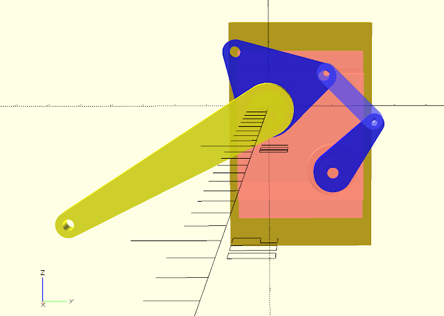
(Blue) knee servo arm, linkage, and co-axial cam
(Yello) Upper-Leg also co-axial, servo connected

Microcontroller and Servo Driver:

For Mojo5, a major change was adopting the ESP32 controller instead of the simpler Arduino mini-pro used in previous Mojo variants. The ESP32 provides added functionality, including built-in Wi-Fi and Bluetooth connectivity, and ample I/O pins to accommodate future expansions.

Mojo5: ESP32 Micro-controller connected to PCA9586 Servo Driver


To drive the servos, I chose the PCA9685 servo driver, utilizing I2C communications. Although my existing 11kg servos are not the most powerful, the PCA9685 still manages to control them effectively. Furthermore, my familiarity with this driver makes it a suitable choice for use with the ESP32.


The Franken-Prototype:

To quickly test the concept feasibility, an initial prototype was assembled. It consisted of a newly designed 'upper-leg' or 'femur' and a knee-cam sharing the same axis as the upper-leg. Other parts were recycled from earlier robots, giving birth to what we affectionately call a 'franken-prototype'. Franken-prototyping is a common and pragmatic approach to quickly determining the feasibility of an idea.

The first test was crucial – connecting the servos to the PCA9685 and ESP32. I taped the servos together and assembled the required components. Powering the system with a 5V source, I eagerly sought to witness the initial motion and validate the success of this build. And to my delight, it worked! This promising outcome lays a solid foundation for the upcoming design iterations.

Mojo5: Franken-Prototype

In addition to the Prototype, I was able to set up a new repository for the Mojo5 code, and test out the basic set up, communications, and loops.

With Mojo5's initial movements validated, I'm excited to delve deeper into refining and enhancing its capabilities for even greater achievements in the future!

Sunday, November 13, 2022

Robot Runner (#5) - The Difference a Gear Type makes!


After the first prototype testing, it was evident that the 'drive gear' was slipping. This is the gear that is directly connected to the 3D printed gearbox. The gearbox itself may have some backlash (flex), but otherwise the system was pretty tight. It was just that the pressure from the leg mechanism was causing the gear to slip.

Here is a short video of the slippage


The fix to this turned out to be a simple change from a regular spur gear, to a helical gear. (the gear with a slant)

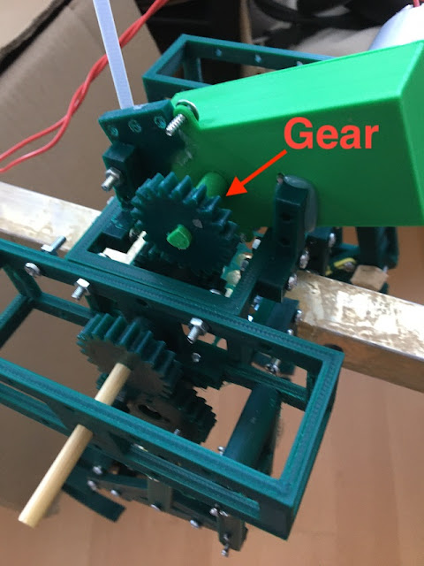
here is the original gear on the gearbox:

robot-runner with original spur gear


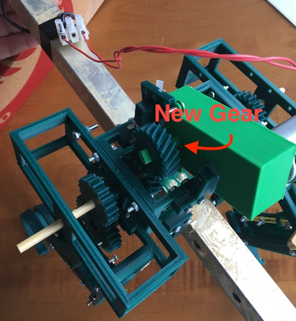
and the new CAD model (OpenSCAD)


This gear design has additional surface area touching in the teeth of the gear.  This is all that was needed to improve the operations.

Helical gears are one type of cylindrical gears with slanted tooth trace. Compared to spur gears, they have the larger contact ratio and excel in quietness and less vibration and able to transmit large force. A pair of helical gears has the same helix angle but the helix hand is opposite.  (hkgears.net)

New gear:

robot-runner with helical drive gear


Second prototype test:  Much better


All and all, I will pause this development for the moment. The mechanism is not performing as well as I would hoped for this point in time. I may return to the design. But, for the time, I am thinking more about a more functional base robot - back to MinOne.

Monday, September 26, 2022

Robot Runner (#3) - Frame and Filling out

 The Runner is getting bigger.  (I really hope this will be able to withstand the weight and keep its balance!)

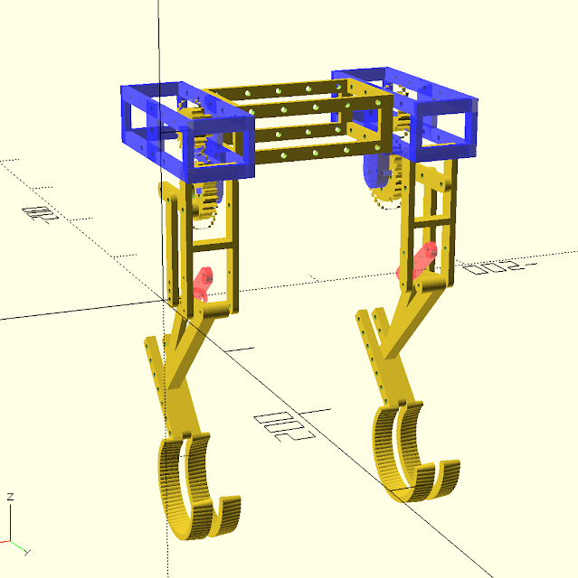
Robot Runner - OpenSCAD - current build 25-sept-2022

This past week's focus was on building out the frame that will support the running mechanism. The location of the crank gear has to be positioned at a specific distance from the fixed pivot point holding the leg.  More important, these two components must be connected to some frame that the rest of the robot can connect too.  AND! it must support the axel that the drive gears will be attached to.  Therefore, it is a lot ton consider in a single piece. 

My first design was close to working, but the placement of the drive gear axel to the crank gear was too far apart by 1-2mm.  The part was worthless! As part of the re-design, I made the frame and the crank gear stantion (holder) to be seperate pieces. This provides some method of adjustment (with washers) in the cast that it needs to be adjusted.

Video:

Here is a video of the current build 'running' - yes it is running backwards!  

Prototype Running Leg Video

I was able to reuse parts from a pervious robot (mojo4) as a stand in for the gearbox chassis. Had this part been 35mm high instead of 40mm, I could have just used that part.

Now that this is somewhat working, I am returning to the leg structure. I am providing some width to the foot, lower leg, and compliant achilles link.

OpenSCAD - Running Robot Foot Design

and printing in the rain...

3D Printing Robot Parts - in the rain


Saturday, September 17, 2022

Robot Runner (#2) - skinny leg gets thicker

The skinny protype leg needs to be wider to support the robot. In general in needs to be more robust and handle the sideways transitional forces. To do this I am making the leg as wide as the 'pin' in my previously designed hinges. This pin is a 40mm finishing nail, which I have a box of. I have used them has hinge pins in the design of the wild weasel and Mojo4.  This will provide some of the support needed for the sideways forces. The design must be carried forward down to the lower leg and foot.

Robot Running Leg Mechanism -v2

As the width of the robot increases, it is not possible to determine on which side the compliant link will go and the placement of the crank and crank gear. The back lifting linkage, does not need to be 'wide' as it is only projecting the motion, not the support.

Robot Running Leg Mechanism CAD (pins not shown)

Also in this step, I am starting to think of how to drive the crank gear with a motor.  I have a 3D printed gear box from a previous design to reuse (Tilt! and 3D gearbox).  This gearbox will allow the robot to be driven by a brushed motor from a recycled printer.

Here is a video of the current design step:


As you can see, there is a lot of movement generated by the motor. The leg is thrown around creating an oscillation and some unwanted impulse movement.  This will need to be considered (dampened)in future design steps.

Saturday, February 5, 2022

Design Iterations - Animatronic Eyes


Design Process

Probably the most exciting part of design work is the incremental improvements in each iteration of the design. the enjoyment comes from trying something, testing it, and then finding a new improvement that can be made. (then of course "realizing" this thing you just thought of)

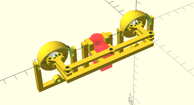
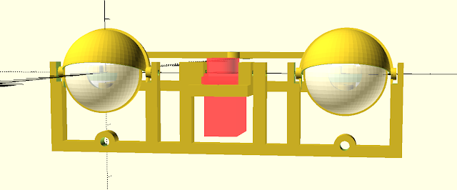
The design iterations of my Animatronic Eyes is a prime example. Currently I am in the middle of this design process where we "Design, Test, Improve, Repeat". I am moving between OpenSCAD, the printer, the assembly and testing, improvements ideas, and Repeat.

Anamatroic Eyes - Early Prototyping (Back)

Animatronic Eyes - Early Prototyping (Front)

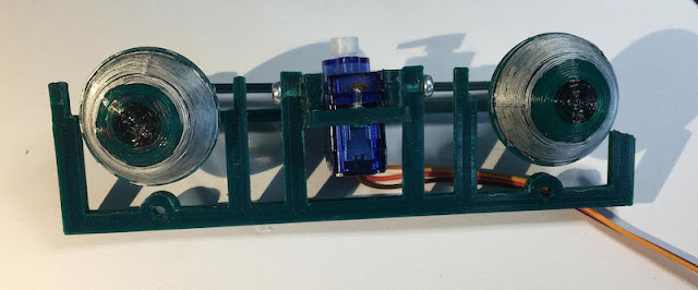
The Early prototype supports most of the ideas of the bigger vision.  The eyes will independently move horizontally (left and right) and vertically (up and down). This will require two servos. In this design the eyes will be held in place by a frame that can (eventually) be tilted vertically. The frame will allow the eyes to be fixed, but a moving armature will provide the horizontal movement. This is consistent with many designs on the internet.

This very early prototype is functional, but quickly pointed out that my hole sizes for screws were all too small as well as the frame size. Note: It also clearly shows my minimalist view toward prototypes and products. It does not work correctly, but it works enough to improve the mistake and to start thinking of the next features (the vertical hinge, Eyes, and eyelids)

Back to OpenSCAD

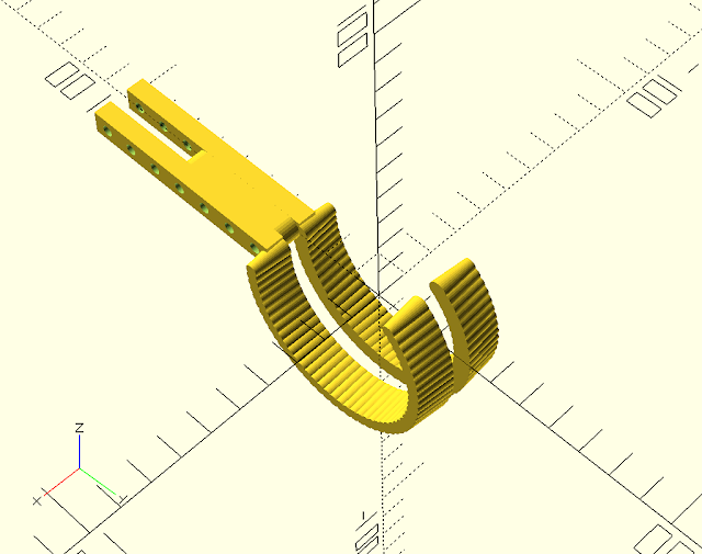
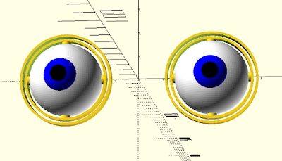
Animatronic Eyes - Prototyping - backside - OpenSCAD

Animatronic Eyes - Prototyping - frontside - OpenSCAD

The next iteration adds primary frame to support the vertical hinge needed to tilt the eyes up and down. This hinge is located centrally and will support the Eye Frame that provides the primary eye support and horizontal servo control. the Frame also Supports for the eyelids. 

This iteration will add the first version of the eyelids. I am starting with the top and a simple hinge method. In some sense all iterations may be 'mixed' between new features like the eyelids and improvements such as full servo mount on the eye support armature.

Printing it out

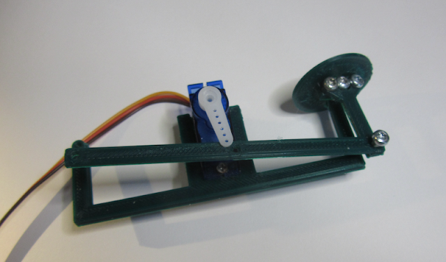
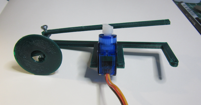
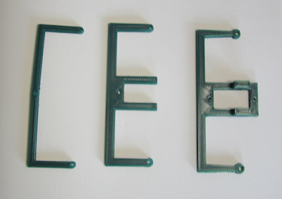
Design Progression of the Horizontal Armature (version 1, 2, 3)

In this picture you can see the progression of the iterations effect on the design.  The first version on the left is just a simple mock up to see if it size of the armature would be good, and the thickness of the frame. Next support for the horizontal servo was added, and the end holes enlarged. Finally the servo support is strengthened, the end holes are strengthened, and support for the vertical hinge is added. Each iteration helps the next, with the first being pathfinders for the future design.

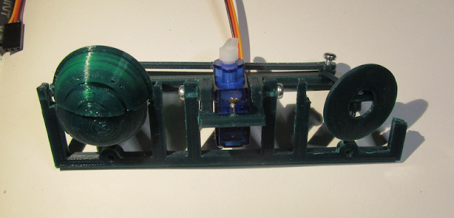
Current Prototype version - Animatronic Eyes

Finally, here is the current printed version of the prototype. Already it is obvious that the lid will need strengthening. I suspected the frame will need to be divided into parts, as it is difficult to manage the hinge pins in both the vertical hinge and the eyelids.

Animatronic Eyes - early prototyping


Onward and Upward!


Saturday, January 15, 2022

Mojo4 - a little design cleanup (#5)

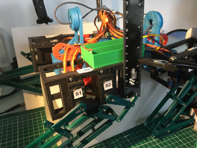
 Mojo4 has regressed in its ability to shuffle across the floor, unfortunately.  This regression could be due to various causes. I have some concerns over the battery current and the condition of the battery given the temperatures and current. It is also obvious to me that the 'Franken-Prototype' nature is having an impact on the testing of the robot.  It seems that the franken-prototype has taken the design as far as it can go, and an upgrade is necessary to continue forward.  on to --

Mojo4 - Robot is a mess, it needs a better frame or chassis

De-Frankensteining

the majority of the robot is currently built with reused pieces. The is due to the focus being on testing how viable the legs will be for walking.  Having (somewhat) proved this, the next steps need to have a more reliable robot platform.  First on the list is to secure the 4 leg units with a better frame or chassis.  I would like to do this in a way that any new parts, will be used in the future robot (as much as possible).

I will create some Frame Sections that will separate the leg modules, a provide a more stable chassis.  Notice how the right side leg modules are actually not aligned with the rest of the robot - this will certainly have impact to the ability to have a precision walk. 

Backward compatible - should not exist as a design constraint of a NEW robot in the prototype stage! But the question comes to mind.  In order to only build the parts I need, I would need to ensure that the new replacement part fit the same configuration of the existing parts. This mean that the new part is 'backward compatible' with the older part.  This, however, wold be a design sin at this stage. It would limit the innovation of the future robot, tying it needlessly to an obsolete part.  

One note, since my parts tend to have regular 10mm spaced holes for M3 bolts, it does provide a lot of reuse potential.  Unfortunately, i found that my previous designs, I was less concerned with 'standard' parts; therefore many of my old parts do not have regular dimensions (around the rounded cm values). This has limited my ability to reuse.  Going forward I will be more careful to make sure parts I design fit into somewhat regular dimensions.

Frame Section:

I have designed a frame part that will help construct the prototype, while also being a useful part for the future build.  This Frame Section is a box of 10cm x 6cm x 4cm dimensions. It will have M3 holes on the outside and a basic 'floor' for holding components (battery box, or Micro controller).

Frame Section - useful and reusable building component

If I print out 3-4 of these, then I can replace most of the frankenstein-prototype parts used to hold the leg modules in place.  This should provide a more robot platform for testing the basic gait and servo strength.


Monday, November 8, 2021

Mojo4 - 5bar design (#1)

Time for A new Mojo Design!  Time to get back in to the wonderful world of Quadrupeds!

I am trying out a new design approach for a new Quadruped.  The 5-bar linkage.  

This approach has been successful in several quadruped designs found on the internet. (one of my favorite is by Oracid: video.) 

It has a full range of motion with only requiring only 2 servos per leg. in addition the leg linkages are supported by pin/hinges on the frame. This should reduce, but not eliminate the force exerted on the servo motors.

Linkages are just mechanical arrangements of bars/links/connectors and pivoting connections. Given different types of configurations, it is possible to get a wide range of applications. One of the most common linkage people have seen on old steam engines. Here, the steam exerts a linear force that is then converted to a rotational force to move the trains wheels.

For a 5 bar linkage, only two bars are connected to the servos. by changing the angle on just these two servos, one can get a wide range of motion.

By I.Elgamal - Own work, CC BY-SA 4.0

For my design, I will be connecting the top two pivot points together to create a 'diamond' of the linkages.  next, at the bottom, the bar is extended further out. Here is where the 'paw' will be connected.

5 Bar Linkage in a diamond with 'paw' configuration

I am hoping that this arrangement of parts should provide significantly more vertical lift in the leg. Mojo2 did not have significant lift and often shuffled.  Also, Mojo3 had more left control, but the servos were overpowered. This combination should provide both the needed strength and lift required.

To control the leg, the two servos will be connected in smaller 4 bar connection to the sides of the Diamond. The key in the design is to keep the servo horns parallel to the bars that they control. In operations, the servos themselves act virtually identical to the top diamonds sides.

Mojo4 Robot Leg design with control actuators

The linkage parts will be 3D printed (of course) and I will be using a small nail as the hinge.  This hinge arrangement is very similar to the track design I used on the Wild Weasel. (video)  Having a reliable design in the CAD and 3D printing makes building robots a lot easier. With this design I can remove a freshly printed part and assemble it with only basic smoothing and cleaning.


For my first rapid prototype testing, I will only have a test stand to validate the movement of the leg. I am re-using parts and the wiring from Mojo2.  I will reuse the Mojo2 servos, MG995 servos. These are 13kg servos. They are slightly heavy for this application at 65g.

Here is what the constructed leg mechanism looks like:

Mojo4 Robot Test Leg

Next Steps:
Now that the basic structure is printed and built for the 'test stand'. I will work on the software to move the leg. For this robot, and the first for Mojo, I will implement some form of Inverse Kinematics. With Inverse Kinematics, it will be possible to instruct the leg the exact position it should talke, and the IK will determine the correct angles to command to the servos.

Monday, August 9, 2021

Tilt! - A Self Balancing Robot (#8) - New Gearbox for Motor and Wheels


A new gearbox for the self balancing robot.

The reuse of the pulley system is not working on the robot. Therefore, I started the whole gearbox design for recycled printer motors.  Now that there is a somewhat functional gearbox, it is time to return to Tilt! and see how the gearbox can be applied.

Here are the parts!  Now, just Engineer a new Motor mount and Wheel assembly!  


Engineer That!

New Motor Gearboxes layout with the old mounting brackets

Rough draft started - the concept of the new mounting system will be similar to the previous design iteration. Now, instead of using pulleys on a wheel with an axel, the axel will be directly part of the output shaft of the gearbox.  There will be a single 22mm bearing to take the load/weight of the robot instead of transmitting that to the gearbox/motor.

New Motor mount and gearbox

The New motor mount is wider than the original chassis and will fit 'around' the existing battery box. This frame will take use of the 1cm holes to allow for easy modular construction.  The gearbox, has new brackets so that it can be screwed to the new mount.  The old wheels are reusable, I will have a friction dependent plug that sets in the hub of the wheel and securely fits the output shaft of the gearbox.

Tilt with new 3D printed Gearbox - more Torque, less speed

NEXT:  Look for the new video showing the assembly of the gearbox. This is not a full instructional video, but does show how a simple gearbox can be 3D printed to allow for the use of recycled printer motors in robot construction.

Monday, June 7, 2021

2021 Game of Shrooms


The Totally Not Evil Robot Army will be participating in the 2021 Game of Shroom - Art Seek -n- Keep.  If you are in Düsseldorf, Germany on June 12th 2021, you can find original Totally Not Evil Robot Army Shroom-Art!

for more details and the Clues - see the page:  2021 Game of Shrooms

you can learn more from the official site:  Game of Shrooms

Goto my Shroom Page for the details and CLUES

The Shrooms are Growing!

Shrooms are next to famous Düsseldorf painter Heinrich Ludwig Philippi

Shrooms in the Wild!


2021 Game of Shrooms - Totally Not Evil Robot Army

Goto my Shroom Page for the details and CLUES

#gameofshrooms #shroomdrop #düsseldorf


Sunday, September 13, 2020

Current Thinking in the Robot Labs

These are things currently being thought about at the TENRA Robot Labs...

Late nights and early mornings in the lab!

3D Printing

Ah... the beauty of 3D printing for robots!   It is the magic of having an idea in your head, which leads to, a sketch on paper, a drawing in CAD, and then a solid print - or many prints:


1st - A quick sketch on paper

2nd - A quick draft in OpenSCAD

3rd - a quick print - a solid Object!

Finally - Repeat as needed

I really love this aspect of Rapid Prototyping. I find it one of the more enjoyable steps in robot building. At each step in the process, you can find opportunities or issues with your design. It is fantastically easy to go back a step or two and add improvement to the design.

A good example is in this very simple build of "Node", pictured above.  "The Node" is an experiment in the Milli Project. I wanted to explore the ability to move in two directions on the helix in order to improve the mobility of the millipede robot. 

At each step in the process, I found that new aspects of the build became evident.  Even in the first print, i realized that I need more of the 'feet' to touch the printer bed. A quick change to parameters in the CAD, and it solved the problem. Finally, a quick print of three copies of the nodes. I assembled them and was able to perform my tests. The result was that the solution would not work as is due to certain bindings. I was having a difficult time imagining this complex relation in my head.  The rapid development of the concept provides a fast path to success or failure, both are acceptable!


Min1 - what should it do at night? 

Min1 is the Minimal Viable Robot for the Totally Not Evil Robot Army.  But, I am just thinking, what can this robot do at night.  It is just sitting around, with nothing to do.  Idle cycles are the devil's playground, right? So perhaps it needs a few teeth and a sensor to seek things (like ankles) out and make stabby motions.  ;)

Min1 - outfitted with ultrasonic sensors and stabby teeth


Min1 ready to Roam - seek and stab


Min1 Robot - as a Franken-prototype ready to go

Tilt!

Tilt, the balancing - 2 wheel Robot, is sitting prominently in the TENRA Robot Labs. It is patiently waiting a more powerful power source.  Twelve Volts DC is not going to cut it, it needs more power to keep the recycled printer motors from stalling.  I have just recycled a 19V power adapter that I will use as 'shore power' for the next round of testing. 

I am really liking Tilts new 'eyes'!