 |
| Typical brushed DC Motors salvaged from old printers |
part 1I love to recycle old electronics and printers for parts. I find taking old printers apart is a fascinating way to learn the mechanics of robots. I now have a nice collection of small 9v, 12v, and 18v brushed DC Motors. This is the basic mechanical part of robots! However, using these motors has proven to be difficult as they often have a high rotation speed and low torque. For robot projects, you typically need the opposite, slower rotation, and high torque. The only way to achieve this is to use a gearbox with the motors. Gearboxes use the mechanical properties of gear-reduction to reduce the rotational rate and increase the torque.
Now it is the time in my robot development to build an accessible gearbox that will work with my projects and recycled motors.
I have worked with gear reduction on a few projects. notably the tank track and wild weasel drive. Discussions about Planetary gears. More recently with Tilt!, using the motors with a belt.
Here is a nice Instructable that i am using for inspiration, "3d Printed Gearbox for Small Dc Motors". It does not mention much on the actual design/engineering of the gearbox. But, it is a nice video and a good place to start. There are plenty of other YouTube videos that also show the capability of 3D printing gear boxes. Remember, it is far too easy to spend (waiste?) time watching others make videos, then just doing it yourself. ;)
Starting from the Beginning
What do I need? (Functional Requirements):
- must work with recycled printer motors
- brushed 9-12V motors
- bare metal spindle
- 16:1 or better reduction and torque
- minimal backlash (movement in the output shaft)
- keep the dimensions to less than 1.5 to 2 size of the motor
softer, but important requirements:
- something easy to print, use, and maintain
- reliable, not prone to jamming
- No stripping of the motor gear interface
The concept:
the motor spins a series of gears, each time a small gear with ess teeth drives a larger gear with more teeth. each stage reduces the rotational rate of the gear that is being driven. There needs to be 4-5 of theses connections. finally it is connected to an output shaft. This is all contained on just 2-3 axels, contained in a box, and bathed in grease.
Let's start with a basic gear:
I am using OpenSCAD for my designs. For gears I highly recommend the Getriebe.scad library from Dr Jörg Janssen, he rocks! It is written in german, but hey? what's wrong with that? ;)
The primary gear will have a large and small gear physically connected. I am starting with 14 and 28 teeth (a ratio of 2) with a modulus of 1.0 (relation between teeth and diameter). I will also use a angle on the teeth on the gear, to help reduce the gears from raising up on their axles when spun at high speed.
 |
| Gear v1 |
Stacking the next gear:
so the big design question, is what is the separation of the gears? this should be the diameter of the large gear minus half the diameter of the small gear plus some tolerance. Now a good engineer will be able to calculate the tolerance needed based on the 'pressure faces' of the gear teeth. however, I am not that engineer today and my 3D printing lacks some precision, therefore I am going to start with 0.5mm. ;)
 |
| Stacking the next gear in place |
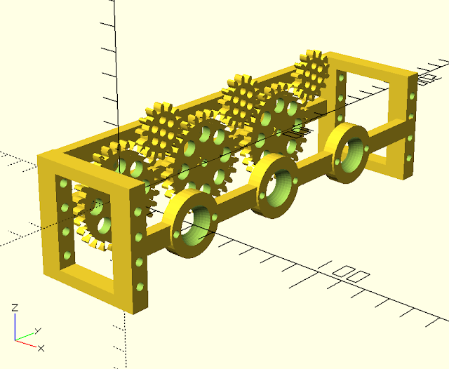
Full gear stack:
Next, add the 3rd primary gear to the top of the first axel.
For the motor gear (Red), I am using the same gear configuration as the small gear, but making it 1.5 taller than the standard gear height.
For the output shaft gear (Green), I am using the same gear configuration of the large gear, but will add a shaft on top of it. For this first build a version, i will just print the shaft as part of the gear. However, this is not good design. The shaft should not be printed, ideally it will be a different material, preferably metal. In fact, this is the weakest part of this design so far. Load bearings should be added to this shaft to absorb the load of the shaft and translate it to the box (or any other non-moving part of the assembly). For now, I will print - it is fast and this is more of a "pathfinder" exercise.
 |
| Full gear stack |
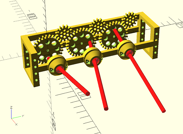
The Box
The gears will be placed inside a box. It will be important to keep the gear from getting foreign matter jammed in the gears. Also, the gears will need some lubricant grease, which will be messy. Most important, the box will provide the structural strength needed to hold the gear axels in place. On one side the motor will be attached. On the other side will be the output shaft and associated load (a bearing would be ideal, next version). In addition, I will add some mounting holes, so that I can bolt the gearbox to my robot creations.
My first design thoughts are to have the motor and the gears attached to a plate that can be screwed on to the box. The rest of the box will be just the compartment, output shaft hole, and mounting support. This part of the box can be printed 'upside down' (see diagram).
 |
| "top view" (no top plate) to make sure all the gears fit |
The CAD view, can be used to visually determine if there will be issues with the screw placements. In this next view you can see the motor (in blue) will over lap the screw positions for the motor plate, as a result, I think i will lengthen this side of the box to compensate. (I also have an issue with the wall placement on the right side)
 |
| Use the CAD views to verify the design |
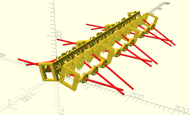
Full Design
drafting out the box and all of the screw holes, will complete the initial design. Now it is time to review the CAD drawing, look for flaws (like forgetting the primary axel holder in the output_shaft_plate). After some adjustments it looks like this:
 |
First full design
|
Time to start 3D printing and testing
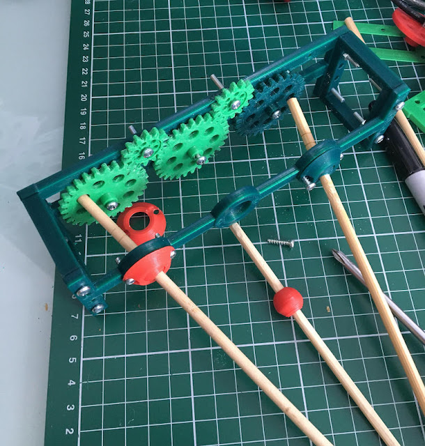
The first results - work, but leave a little to be desired. I assembled the motor, gear, and the three primary gears together. I used nails as a quick axel. Hooking up about 8V of power, it gave it a quick spin. It does work! This test was outside of normal operating conditions as it will be enclosed in a box and axles will be supported on both ends. The operations were a little rough (no grease!). Therefore I did not post of video of it. Here are some pictures.
 |
| Gearbox version1, first print |
 |
| Gearbox version1, top view |
Next Steps
For the next steps on this project, I will be making adjustments and some improvements. Primarily I will reduce the number of teeth, and increase the modulus. This should result in a similar sized output, but with less teeth. I believe the lower number of teeth will print easier on my 3D printer. I may also add a few mm to the size gears as well. Check back to see on the next post.
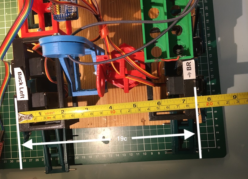
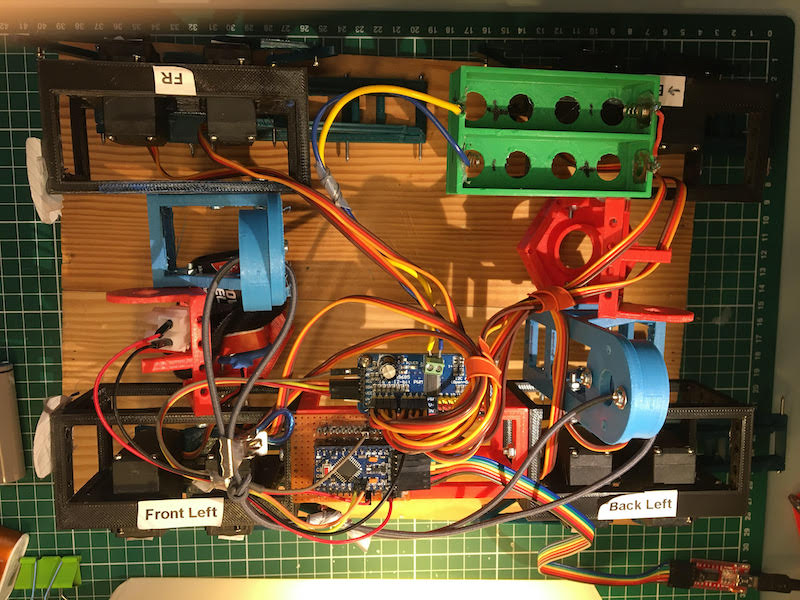
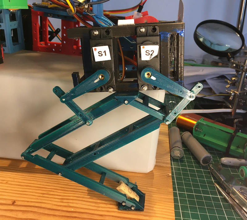
 it is built mostly with reused 3D printed parts. All of the Dark Green Leg parts were printed so that I could experiment with the 5-Bar design. Everything else is reused or scrap from previous projects. This includes the black frames used to mount the servo motors. My plan is that once this is walking, I will start printing a new chassis with my new-found experiences, also to add the 12DoF. But first this one must walk.
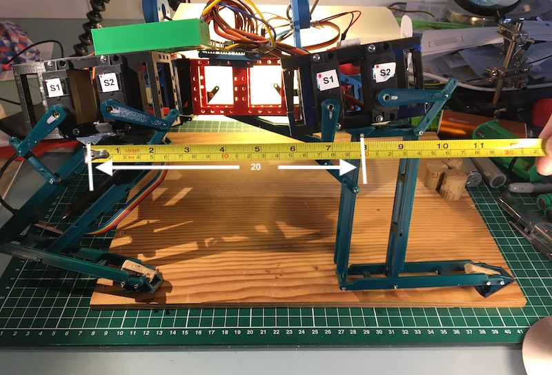


 vs Current version (below)")


