Showing posts with label Bio-Inspired Robots. Show all posts

Sunday, August 11, 2024

Mojo5: The End of a Journey (#12)


Every project reaches that pivotal moment when progress halts, and the creative spark seems to fade. For Mojo5, that moment has arrived. This little robot has encountered a significant challenge in the design of its abductors. The servos have developed excessive backlash, compromising its ability to stand and walk effectively.

In an attempt to resolve the issue, I removed the servos and installed a 'static' gear to lock them in place. Unfortunately, this fix didn't fully eliminate the backlash, and the problem persists. Addressing this issue would require a major redesign, far more extensive than initially anticipated.

With a heavy heart, I’ve decided that it’s time to retire Mojo5. But as with all endings, this marks the beginning of something new. Long live Mojo6.

Saturday, January 13, 2024

A more RUGGED robot platform for Exploration

continuing on the these of robotic design, with the help of AI (robotics) tools... 

 It seems our last attempts resulted in an unexpected robot! The broad pink and white stripes, soft lighting, and big goofy grin resulted in a "Total Adorable Robot".

Extra Adorable, Totally Not Evil Robot

However, I do not think that that Robot would survive very long in the Sonoran Desert!  There for, back to the discussion, and lets add some design that would work in a sandy, rocky region:


The first in the conversation, when reminded that the robot needed operate in rocky or sandy environments, it added broad wheels in an awkward arrangement.  I could imagine this also as a treaded solution. The bigger innovation perhaps is having the sensor platform as a (potentially) pivoting top component over the drive chassis. The streamlined frame looks like it would handle wind storms much better. The front sensors and display may need some protection and covering. overall, this is a much more robust robot.  But where is the manipulator arm?

The next variation of the prompt placed the robot in an icy, rocky environment and requested it have a manipulator that inspects geology:


The wheels of this Robot are considerably more realistic. It is also quite plausible that this robot would fall over. If you examine closely, there is a suggestion of the manipulator arm jutting out between wheels, but it gets blended into the axel and is lost. 

The next request required that the manipulator be the focus of the image.


This version has even more rugged wheels and a top structre that looks like it could support a wide variety of payload. The manipulator arm is placed in a difficult position, but looks robust and effective.

The Rugged, Wheeled Hexapod:

What if the Wheels of the robot were replaced with rugged manipulators with wheels? The robot could crawl over rocks. Here is a potential variant:


I like this concept robot a lot. It would require very strong actuators and some compliant joints. By having some wheel motion capability at the end of the manipulators, the robot could roll and climb in difficult terrain. The top structure has the appearance of a turret, to move to present its sensors in all directions.

There is a lot of potential with a robot design like this.

For those interested in learning how OpenAI's ChatGPT and DALLE-3 work, the last three images were all generated using the exact same prompt. Here you can see how variation is introduced when executing the same prompt.


and once again:


Prompt: 
A robust, medium-sized exploration robot designed for rugged terrains, now uniquely featuring six multipurpose manipulator arms, used for both agile movement and examination. The robot has no wheels and moves by crawling on these manipulator arms. The body of the robot is adorned with broad pink and white stripes, presenting a friendly appearance. It has smooth, rounded contours, similar to an animal-like form. A digital display on the front shows a goofy grin, adding to its welcoming demeanor. The manipulator arms are made of strong, lightweight material, matching the robot's color scheme. These arms are intricately designed, demonstrating their flexibility and dexterity as the robot crawls across a challenging landscape, using them to navigate as well as examine geological features. Soft, warm lighting and clear branding with labels like 'Research Robot' and 'TOTALLY Not Evil!' are included in the design, with a focus on the unique functionality and design of the manipulator arms in the rugged environment.

Interesting what might actual make these images unique.  Once rendered it would be almost impossible to re-render the exact same picture.  See for yourself how very different they are drawn, given the same instructions.

Of course, they are all supposed to have six arms, and the last two only have four! They are also each supposed to have "Research Robot" and "Totally Not Evil!" stickers on them. It seems we stil have some more learning and progress to get DALLE3 on task, even when it was in a moderated thread with ChatGPT.


Sunday, November 13, 2022

Robot Runner (#5) - The Difference a Gear Type makes!


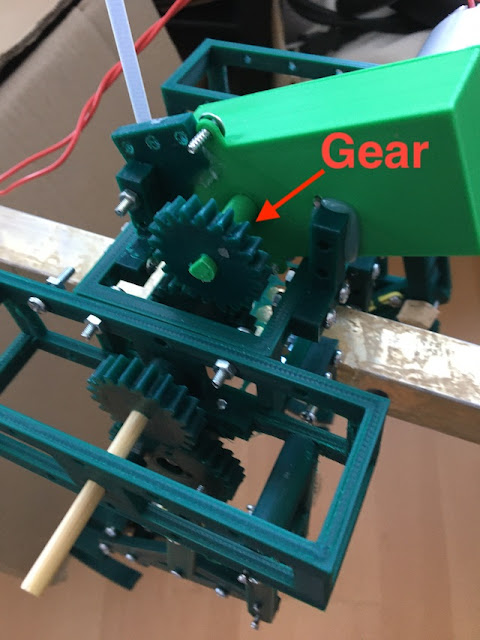
After the first prototype testing, it was evident that the 'drive gear' was slipping. This is the gear that is directly connected to the 3D printed gearbox. The gearbox itself may have some backlash (flex), but otherwise the system was pretty tight. It was just that the pressure from the leg mechanism was causing the gear to slip.

Here is a short video of the slippage


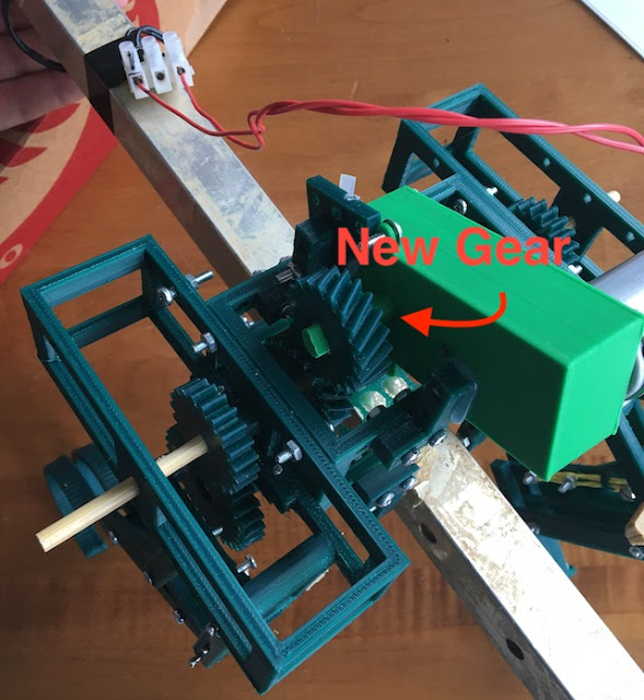
The fix to this turned out to be a simple change from a regular spur gear, to a helical gear. (the gear with a slant)

here is the original gear on the gearbox:

robot-runner with original spur gear


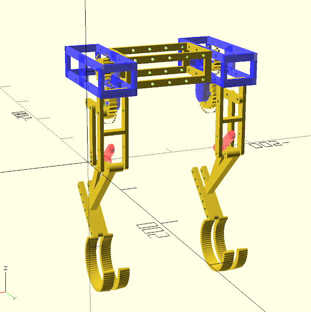
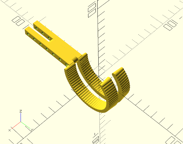
and the new CAD model (OpenSCAD)


This gear design has additional surface area touching in the teeth of the gear.  This is all that was needed to improve the operations.

Helical gears are one type of cylindrical gears with slanted tooth trace. Compared to spur gears, they have the larger contact ratio and excel in quietness and less vibration and able to transmit large force. A pair of helical gears has the same helix angle but the helix hand is opposite.  (hkgears.net)

New gear:

robot-runner with helical drive gear


Second prototype test:  Much better


All and all, I will pause this development for the moment. The mechanism is not performing as well as I would hoped for this point in time. I may return to the design. But, for the time, I am thinking more about a more functional base robot - back to MinOne.

Thursday, October 6, 2022

Robot Runner (#4) - two legs running video update

Running Dinobot - by Dalle2 & Doug


Here is the progress on the running robot...

a (literally) short video:


Perhaps I need a little help from another robot to visualize a potential application?  Here are some options from DALLE-2 and Me!  Which do you like?


Running Dinobot - by Dalle2 & Doug

Running Dinobot - by Dalle2 & Doug

Running Dinocyborg - by Dalle2 & Doug


Monday, September 26, 2022

Robot Runner (#3) - Frame and Filling out

 The Runner is getting bigger.  (I really hope this will be able to withstand the weight and keep its balance!)

Robot Runner - OpenSCAD - current build 25-sept-2022

This past week's focus was on building out the frame that will support the running mechanism. The location of the crank gear has to be positioned at a specific distance from the fixed pivot point holding the leg.  More important, these two components must be connected to some frame that the rest of the robot can connect too.  AND! it must support the axel that the drive gears will be attached to.  Therefore, it is a lot ton consider in a single piece. 

My first design was close to working, but the placement of the drive gear axel to the crank gear was too far apart by 1-2mm.  The part was worthless! As part of the re-design, I made the frame and the crank gear stantion (holder) to be seperate pieces. This provides some method of adjustment (with washers) in the cast that it needs to be adjusted.

Video:

Here is a video of the current build 'running' - yes it is running backwards!  

Prototype Running Leg Video

I was able to reuse parts from a pervious robot (mojo4) as a stand in for the gearbox chassis. Had this part been 35mm high instead of 40mm, I could have just used that part.

Now that this is somewhat working, I am returning to the leg structure. I am providing some width to the foot, lower leg, and compliant achilles link.

OpenSCAD - Running Robot Foot Design

and printing in the rain...

3D Printing Robot Parts - in the rain


Saturday, September 17, 2022

Robot Runner (#2) - skinny leg gets thicker

The skinny protype leg needs to be wider to support the robot. In general in needs to be more robust and handle the sideways transitional forces. To do this I am making the leg as wide as the 'pin' in my previously designed hinges. This pin is a 40mm finishing nail, which I have a box of. I have used them has hinge pins in the design of the wild weasel and Mojo4.  This will provide some of the support needed for the sideways forces. The design must be carried forward down to the lower leg and foot.

Robot Running Leg Mechanism -v2

As the width of the robot increases, it is not possible to determine on which side the compliant link will go and the placement of the crank and crank gear. The back lifting linkage, does not need to be 'wide' as it is only projecting the motion, not the support.

Robot Running Leg Mechanism CAD (pins not shown)

Also in this step, I am starting to think of how to drive the crank gear with a motor.  I have a 3D printed gear box from a previous design to reuse (Tilt! and 3D gearbox).  This gearbox will allow the robot to be driven by a brushed motor from a recycled printer.

Here is a video of the current design step:


As you can see, there is a lot of movement generated by the motor. The leg is thrown around creating an oscillation and some unwanted impulse movement.  This will need to be considered (dampened)in future design steps.

Sunday, September 11, 2022

Runner Robot (#1)

I am search of a fast running quadruped (so that I can compete in the Toulouse Robot Races).  I am considering this running mechanism and driving it with a single brushed motor.

This mechanism has worked or others in scholarly papers. I am doing a number of modifications to try to get it to work in a quadruped format.

Robot Runner - Robot leg mechanism

My initial prototype has provided a feasible solution. The mechanism should be able to provide a good profile for walking. I have added some compliancy to provide additional ground contact. From the picutre you can see some of the lengths I have tried for the various linkages. By adjusting these lengths, you can change the step profile.  A profile that has enough rise, and forward movement is desired.

Here is a video of the movements:


The mechanism works well enough in a 2-D plane. This also could have been simulated in programs like Algodoo.  

Next is a tricky issue, the robot will encounter a lot of side loads. Now the mechanism must be designed to reduce the stress of the sideload and transfer (as much as possible) to the chassis of the robot. The image below shows how 'skinny' the "2-D prototype" was.

Side view of the Running mechanism


Follow along to see the progress!

Wednesday, September 7, 2022

In Search of a Stable Robot Leg

This robot leg does not exist. -DALL-E & Doug

I am in search of a "Stable" robot leg.  Stable would mean that it can stand on its own without having to be activity lifted by the motors. In addition, it needs to be able to perform the basic function of lifting and moving in a 3 dimensional 'workspace'.

From a design perspective, lets go over a few requirements:

  • Ability to stand freely supporting its own weight, and preferably some payload
  • Ability to with stand some flexibility, some compliancy
  • Ability to be raised and lowered with in some 'workspace' using up to 3 degrees of freedom (typically 3 servos)
  • Use off the shelf servo motors, springs, 3D printing (PLA), and other common components.

With a stable leg, a biped or quadruped could be realized.


Mojo leg variants:

Here are the iterations of leg designs have I tried so far for the Robot Army.

Leg 1 - Mojo

This was a very primitive first step.  but it has the features of compliance in the two springs.  Obviously it could not support its weight.  This was my first prototype and if you are interested in this kind of stuff - just do it! everyone has a first iteration.

the glass is half full!!


Leg 2 - Mojo2

Mojo2 was a significant improvement in design and lead to a viable walking quadruped. The leg is driven by 2 servo motors. it has a compliant spring to provide stability to stand without motor assistance. The knee was actuated by a servo on the main chases that pulls a cam with a cable to the knee. This cam structure will lift the foot (lower leg) and works against the compression spring providing compliancy.

The issues with this design were centered around the ability for the leg to hold the weight of the robot against the strength to move the leg.  At high duty cycles, the leg would drag along the floor, creating more of a shuffle. Overtime, the cable was prone to stretching, which reduced the performance.  The over all vertical workspace was very limited due to the amount of compression allowed by the spring.

More information can be found on the project pages for Mojo2.

Mojo2 - Quadruped Robot Leg

Leg 3 - Mojo3

The next design tried to remove design flaws in Mojo2. This design removed the forces being directly applied to the servos by introducing bearings. Servo motors only needed to turn gears, without having the weight of the robot transferred through the servo itself. The gears helped in this regard, but it was not obvious how to create compliancy in the design. 

The design on the left hand was functional, but only provided a very small work space of only 4-6 mm. This video shows the amount of workspace available. The gear pinion on the right design, suffered from gear slippage.

This design also attempted to use 9g servo motors in a very small robot. ultimately, the servos could not provide the performance need to make the robot walk.

Mojo3 - quadruped robot leg designs


Leg 4 - Mojo4 - the 5 bar design

In a completely new direction, the next design featured 2 servos moving parallel linkages similar to SCARA robot arms. The geometry of the legs was very important to simplify the calculations of the Kinematics. This is the first robot design where I was able to determine and code the kinematics. The workspace in a non-weight-bearing scenario is very large.

Unfortunately ... this design requires the servo motors to activity support the robot. This creates a large power draw which can limit the performance when all servos are firing. Other makers using this design have worked around this issue by introducing elastic bands to keep the leg standing, and reduce the power needed. With an upgrade this leg can be redesigned, it would require elastic (pulling) springs verses compression springs. For the scale of this leg (>20cm) it is has not been easy to source the springs.


Mojo4 - Five-bar style robot leg

New Designs:

Bipedal Legs 

In my research on the internet, I found variations of a bipedal robots that use just 2 servos per leg for the hip and knee joints, with additional compliant linkages for support. The sideways motion provided by a 3rd servo located in front.  This design is by Yuhang Hu, you can see it in action in his Bipedal Robot video.


Yuhang Hu - Bipedeal Design


Disney's researchers took different approach, instead of the Z axis being a single servo, they connected 2 of the leg/knee legs together with a linkage for a single leg. This provided some stability, but doubles the amount of servos to be used.

Here is my first cad/print sketches. I have spent my initial development just building the bracket for the servo motor so that it an have rotation from both sides. This view is also hacked together with parts from another robot, just to get a feel for the connection points and where a potential spring(s) would need to be placed.  It was not immediately obvious that this design will fit the criteria.

note:  it looks like a step back in design, but this is just the initial drafting and sizing.  also, the basis for thoughts for this blog entry.

prototype-printed-sketch of a 2 dof robot leg.

While building the above, I also found a potential mechanism that could create a running robot with minimal motors.  Perhaps a mechanism instead with the use of a single brushed motor as the actuator.  

Here is an interesting experiment: Design of biped robot inspired by cats for fast running (by: 
Jongwon Park,Young Kook Kim, Byungho Yoon, Kyung-Soo Kim, Soohyun Kim ) One aspect of using a motor, the rotation will easily provide circular X and Y motion.  The motor is located at O2 and the Hip Joint is statically mounted (to the robot frame).

Design of a Biped Robot

My initial version of this running mechanism.  This is just a printed 'sketch' used to determine sizing and placement of the connectors and screws.  The black bar is a placeholder for a compliant link that will be a tension spring (a spring that is pulled).  the wheel at the top will be driven by a single motor, after some gear reduction. The cam/crank that is attached will need to be short, as in this picture. The distance traveled by this cam has a dramatic impact on the movement of the foot.  the bar at the top, represents the framework that the mechanism is attached to. only the top connection and the wheel is fixed to the frame.

Simple Running Robot Leg Mechanism

Here is a YouTube Short of the the mechanism.


I will be starting a new robot series trying to build a fast running robot with minimal motors. That is the motivation for finding the Stable Robot Leg. The end goal is to create a creature like below, for the Toulouse Robot Race in Nov 2022.  :D

Polecat robot sketch


Monday, June 6, 2022

The Robot Menagerie

It's a great time to be building robots.  Today, there are many robot variants that mimic the biology we see in nature. Here is a collection of a few.  I think this is amazing. At the same time it is fantastic that there are a lot of interesting robots yet to be built, both familiar and alien.  There are no limitations to that which we can imagine. 

Robotic Animals - Bio-inspired Robot Menagerie

The dog

Everyone knows Spot the Boston Dynamics Dog.  There are many many quadruped robots - it is really more of a robotic-question of how to implement the legs. I won't go into any more details here since Quadrupeds are becoming so common to us. Dogs, Cats, Mules, Chetas, etc!  

Original Mojo - Robot Dog design


The interesting thought is how can the envelope of capabilities be expanded, speed, stability, terrain, heights, etc.  Just thinking of what robot videos you have seen, how many have quadrupeds climbing steep rough terrain?

robotic fish

Fish are an interesting twist. There are a few notables.. including this 'spy robot':

Robot - Spy Fish:  Charlie the CIA spy fish.  

The Eel - Eelume Undersea robot for undersea inspection use cases.

Another fish:  BlueSwarm  (IEEE spectrum article)


Robotic Snakes

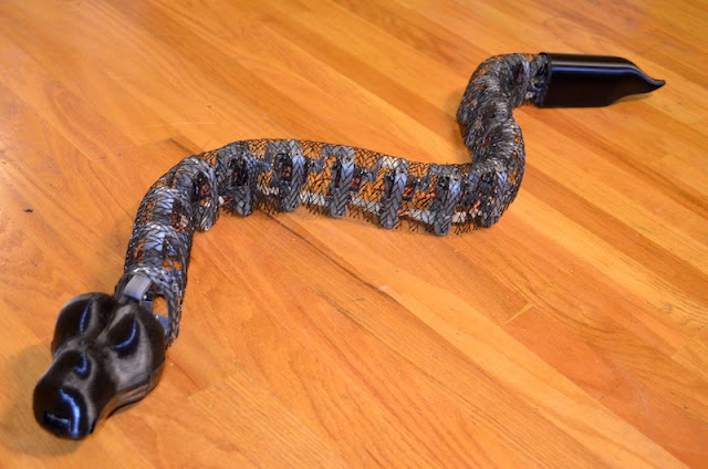
The Slitherbot:  posted on Hack-a-day Slitherbot

Slitherbot - hackaday.io

TESLA Snake:  This was really a automated Charging Connector prototype. It is best viewed in YouTube at x2 normal speed!


Bionic Menagerie

And then there is Festo!!  Festo is a German company that specialized in automation.  The have a lab that produces bionic innovations which cover a full spectrum of animals.  Anyone (or all of them) of which would be an internet sensation. [makes me wonder why we don't see them more in the wild. ?]

Bionic Swift


Bionic fin Wave - this one is great for swimming in pipes.  Also very similar concept to the motion available for my Millipede project.

Insects:

bionic Ants (Festo) - a natural for swarms too.

Centipede Robot - for getting into hard to reach places


And animal robots are a clear cut winner for pets - more companion animals:

Companion Cats


Animatronics - let's make humans! at least human parts... 

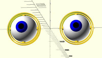
The Eye

this is about the creepiest eye camera there is to date!  It is wonderful! :D


The Claw!

Mark Sen...


and on Tested:


Summary - there are many instances of biomimicry. It is in our very nature to anthropomorphize robots so why not start to build directly in the medium?

There are so many instances of this in our world. this may have to be the first installment. I have waited some time to make this post. It will just need to be an ongoing series.

Saturday, January 8, 2022

Starting Animatronics

 Interested in Animatronics?  I always have been.

I guess the best place to start are the eyes - "the mirrors of the soul" - and the one thing that all humans look at.


There are a few videos on YouTube that go in how to make these.  I will start my design process on it. 

The challenge is having both Vertical and Horizontal movement.  The quick survey I have done suggests that for a typical animatronic, both eyes need to move the same direction and pointing.  Also, it seems to be really cool, you need eye lids.  That will add a few more servos to the mix.

more to come..

Saturday, December 18, 2021

Mojo4 - Additional Details (#4)

Here are some more details of Mojo4 - Quadruped Robot Dog

  NOTE:  This is a FRANKENSTEIN Prototype. ;)   it is built mostly with reused 3D printed parts. All of the Dark Green Leg parts were printed so that I could experiment with the 5-Bar design.  Everything else is reused or scrap from previous projects.  This includes the black frames used to mount the servo motors.  My plan is that once this is walking, I will start printing a new chassis with my new-found experiences, also to add the 12DoF.  But first this one must walk.


Here are the pictures:


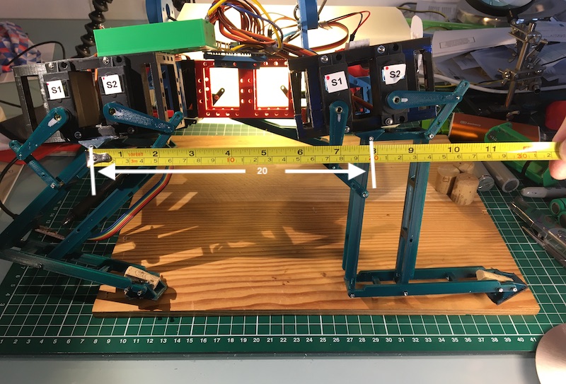
mojo4-length-18dEC.JPG
Length - measured from the pivot points:


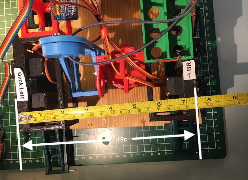
mojo4-width-18dec.JPG
Mojo4 - Width measured on outside legs


Top - Yes, this collection of PLA is a mess.  

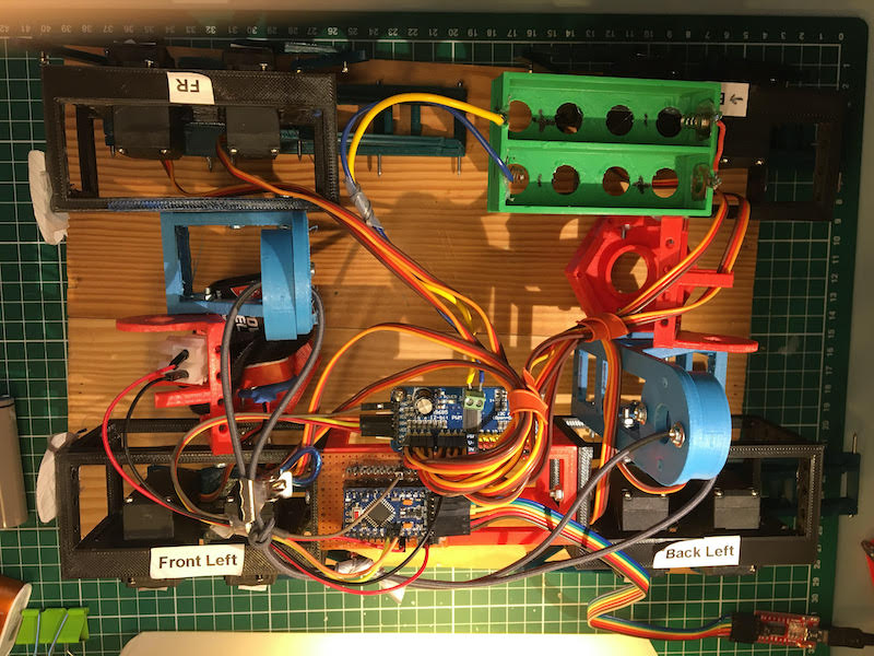
Electronics:  Arduino Pro Mini clone, PCA9685 servo driver, and battery box. 


The 4 servo boxes are on the sides all held together by random parts that fit, bolted together by M3 screws and nuts, some super glue, and hot glue.  Somewhere in there is a 9V battery for the microcontroller, there is a small power switch on the mounting board.


mojo4-top-18Dec.jpeg


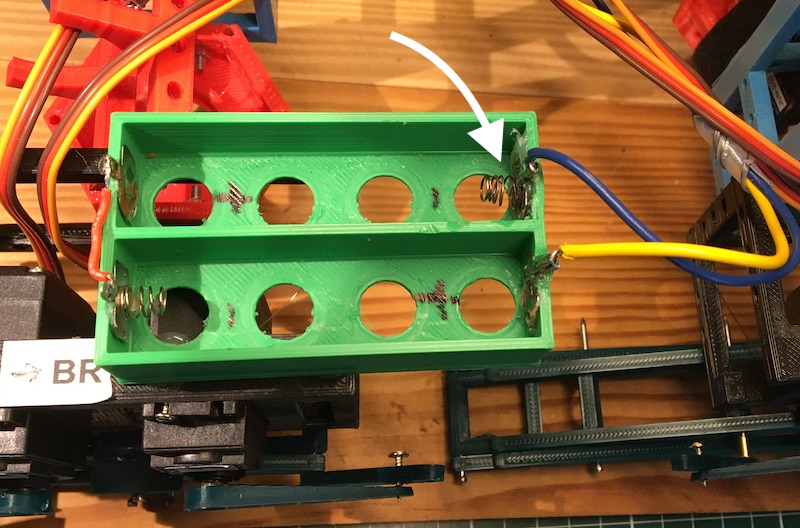
Battery Box:  3D printed, for 2x 18650 batteries. I reused the spring contacts from small toys.  This is a problem since the spring that I have highlighted with an arrow can not handle the current of the batteries and heats up (to the point of melting the hot glue holding it in place).  something else to fix. ;)


mojo4-battery-box.JPG
3D Printed Battery Box for 2x 18650 batteries


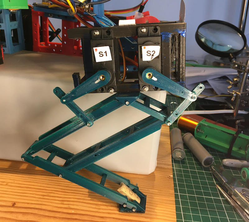
Here is a picture of the leg configuration.  3D printed, minimal material.  It has been strengthen (i made it thicker) to prevent bending. The pivot points are small common nails placed into tubular channels in the leg components. a very cheap easy way of making a hinge. The paw needs a new design.  the current version is 3D printed, has rubber on the bottom, and part of a wine cork to hold it in place.  reuse!  ;)


mojo4-leg-18Dec.jpeg
Mojo4 - 5bar quadruped robot leg


Sunday, December 12, 2021

Mojo4 - Stable Walk Testing (#3)

 Mojo4 - the Quadruped Robot Dog - is now undergoing some very basic walking tests.  Here you can see a video of one of the attempts.  There have been a number of issues found:

- Width - much wider now

- Current Draw from battery, is heading up the 'spring' used to hold the rechargeable batteries in place.

- Feet, getting the right grip

- Leg positioning.  Hind legs back, front legs more forward

- Basic gait, perhaps raise the legs up a little more on the return

Video:


Sunday, November 21, 2021

Mojo3 - A Robotic Dog (#11) - Wrapping up the Design

Mojo 3 has been a good learning experience, but for now i will shortly be moving to a 5 bar design and more complete robot concepts.

Here is the latest video:


Summary

I really like the small compact design of Mojo3. The prototype fit nicely on my desk. It is easy to assemble and did not take long to print on the 3D Printer.  I intentionally made it smaller than Mojo2 in order to get it to work with small 9g servos.

Also in this design, the weight of the robot was carried from the legs directly to the chassis through a 8mm (skateboard) bearing. This is a significant improvement over Mojo2.

Finally, I took the 'compliance' part of the robot out of the design. These legs are driven strictly by the servos, and gears attached directly to the servos.  This approach has the advantage of providing the most direct torque to the leg components. 

Unfortunately the Knee arrangement with a gear and type of pinon/cam, does not work.  It was easy to calibrate. You could just lift the arching gear teeth and put them in the right locations.  However, once the robot was under load, it was prone to slip.  The video shows this very clearly.

Going Forward

I have started a 5 bar leg design.  This arrangement should be easier to get a full range of motion. The next design will incorporate Inverse Kinematics. I will try to write some meaningful blog entry on that.

Monday, November 8, 2021

Mojo4 - 5bar design (#1)

Time for A new Mojo Design!  Time to get back in to the wonderful world of Quadrupeds!

I am trying out a new design approach for a new Quadruped.  The 5-bar linkage.  

This approach has been successful in several quadruped designs found on the internet. (one of my favorite is by Oracid: video.) 

It has a full range of motion with only requiring only 2 servos per leg. in addition the leg linkages are supported by pin/hinges on the frame. This should reduce, but not eliminate the force exerted on the servo motors.

Linkages are just mechanical arrangements of bars/links/connectors and pivoting connections. Given different types of configurations, it is possible to get a wide range of applications. One of the most common linkage people have seen on old steam engines. Here, the steam exerts a linear force that is then converted to a rotational force to move the trains wheels.

For a 5 bar linkage, only two bars are connected to the servos. by changing the angle on just these two servos, one can get a wide range of motion.

By I.Elgamal - Own work, CC BY-SA 4.0

For my design, I will be connecting the top two pivot points together to create a 'diamond' of the linkages.  next, at the bottom, the bar is extended further out. Here is where the 'paw' will be connected.

5 Bar Linkage in a diamond with 'paw' configuration

I am hoping that this arrangement of parts should provide significantly more vertical lift in the leg. Mojo2 did not have significant lift and often shuffled.  Also, Mojo3 had more left control, but the servos were overpowered. This combination should provide both the needed strength and lift required.

To control the leg, the two servos will be connected in smaller 4 bar connection to the sides of the Diamond. The key in the design is to keep the servo horns parallel to the bars that they control. In operations, the servos themselves act virtually identical to the top diamonds sides.

Mojo4 Robot Leg design with control actuators

The linkage parts will be 3D printed (of course) and I will be using a small nail as the hinge.  This hinge arrangement is very similar to the track design I used on the Wild Weasel. (video)  Having a reliable design in the CAD and 3D printing makes building robots a lot easier. With this design I can remove a freshly printed part and assemble it with only basic smoothing and cleaning.


For my first rapid prototype testing, I will only have a test stand to validate the movement of the leg. I am re-using parts and the wiring from Mojo2.  I will reuse the Mojo2 servos, MG995 servos. These are 13kg servos. They are slightly heavy for this application at 65g.

Here is what the constructed leg mechanism looks like:

Mojo4 Robot Test Leg

Next Steps:
Now that the basic structure is printed and built for the 'test stand'. I will work on the software to move the leg. For this robot, and the first for Mojo, I will implement some form of Inverse Kinematics. With Inverse Kinematics, it will be possible to instruct the leg the exact position it should talke, and the IK will determine the correct angles to command to the servos.