Showing posts with label Camera Rover. Show all posts

Wednesday, June 24, 2026

The Ferret - Tunnel Exploring Robot (#1)

TNERA - The Ferret Robot - AI Concept Art

Introduction

I always had a dream in the back of my head about having a robot to go into tiny spaces that I could not. To go down the proverbial rabbit hole and see what is there. This is my goal, to build exploring robots. Even ones that could be recast as pipe-inspection robots. 

Sounded to me like it would be a good weekend project, it also sounded like a good 'new' project that I could test out the capabiltities of using the current AI tools to help build the components. It would be a good test to see how they have improved in the last year. 

So, down the rabbit hole we go! Chasing the AI white rabbit!

Like it or not, We are living in a moment in time in which AI has created a time of software abundance. It is now far easier for individuals to create complex new software with ease. There’s a growing claim, a belief, that "Now anyone, can build anything". Many software Makers are doing just that: they are going back to previous projects that were to onerous to build in the past, and now building them.  

Can this be true for robotics projects as well?

Robotics has always been one of those domains that resists simplification. It is a heavy concentration of software, firmware, electronics, and mechanical design, all interacting in ways that tend to create complexity instead of removing it. Historically, that complexity has been a barrier for automated tools, it also makes it fantastically more interestings.

So this project—The Ferret—is my attempt to explore whether modern AI tools can meaningfully compress that complexity.

The Idea: A Burrow-Exploring Robot

Abandoned Burrow Hole - to be explored

I’ve had this idea for years: a small robot that can crawl into spaces people can’t—burrows, holes, confined environments—and explore them remotely.

To do this, I need something narrow. Cylindrical. Tracked.

A robot that can push forward into an unknown space with a camera and light, acting as a remote presence where a human simply can’t go.

The Core Challenge: Does current AI help here?

Any robotics project sits at the intersection of three domains:

  • Firmware - software that runs on the device
  • Electronics - how components are wired and powered
  • Mechanical design - what the robot physically exists as

AI is clearly strong in firmware and all software development. This part has already become trivial with early 2026 LLMs. Write a good prompt on what you want the firmware to do, and the AI agents can write it for you in minutes.

But how can AI be used to Generate usable 3D printable CAD? used to help design mechanical systems? or provide meaningful assistance with circuitry? This is the real test.

Starting Mechanical Design

The process started not in CAD, but in conversation. Before building anything, I worked with an AI session to:

  1. Define constraints 
  2. Explore design options 
  3. Clarify tradeoffs 
  4. Generate prompts that would later drive development

This turned out to be a useful pattern: design through dialogue first, implementation second.

OpenSCAD and the Nose Cone

I use OpenSCAD for CAD work. It is openSource, and completely codified, which makes it easy for an LLM to write the design in.

Historically, AI has been… really bad at it. Almost unusable.

So I started manually, designing the front of the robot—a nose cone. I knew what I wanted geometrically, but not what to call it. So I asked Gemini Flash. It identified the shape as an elongated ellipsoid, common in aerodynamic designs, and even generated OpenSCAD code for it.  I pasted it in.

It worked immediately.

That was the first signal that something had changed.

Building the Tracks

With that success, I quickly moved over to the design of the caterpillar tracks. This wasn’t my first time building tracked systems (see the Wild Weasel). I had a good mental model of how it should work.  The AI suggested I use Linked track system, where there are two distinct parts like a bicycle chain or chain on a chainsaw. There is some benefit of the cog locking of that method. However, I would prefer a universal (continuous) track system based on preference and past experience. The continuous track uses a single universal track tread that is much easier to print in mass.

The Ferret Robot - Single Track Piece CAD design

The Ferret Robot - Track Pieces in line CAD design

I spent about an hour designing the first track segment manually. It worked well.  a base tread, with a hinge that I could insert small metal rods into. Then, I asked GPT to generate a similar design based on my comments. The initial CAD code output was not very useful. However, I uploaded my design as a rough guide not fully spec'd out, and the AI was able to match and complete the track accurately. The AI was not perfect 'from scratch' like the nose cone, but it was highly effective when guided. 

The Hard Part: Sprockets

Honestly, tracks are easy compared to sprockets. Sprockets are like gears, but they pull chains or track treads instead of meshing with other gears. The geometry of a sprocket is very different to a gear. To work correctly, sprockets require: precise tooth geometry, correct spacing, proper engagement with the track, provide alignment, and support tolerances. Designing a working sprocket is tedious and error-prone.  Another good test of the AI!

The Ferret Robot - Sprocket CAD design

From above, I input the track design to GPT and provided a vague prompt to design a sprocket to fit the track. It did it in less than a minute. The AI generated the geometry, selected a tooth count, and calculated spacing and the included offsets. The design looked impressive, I added an axel and printed it to test.

Again, I found that the design didn’t work perfectly the first time—but it was close. It is not untypical in sprocket design to iterate through small variations to get the right fit and tolerances. This time, instead of manually editing the openSCAD code, I simply described the problem in plain language and let the AI adjust the design. It took five iterations to get a perfect fit. The only parameter I had to tune was offset, which is exactly what you’d expect in manual iteration anyway.

The Ferret Robot - Sprocket sizing iterations. Final on Right
Tensioner and frame on top with sprocket
Track tread length on bottom 

The key difference: I never had to reason about sprocket geometry directly. The sprocket design was custom, not a library. the AI built the hub and teeth on its own. That’s a new skilled behavior to me, the AI has come a long way!

Initial mechanical design assessment

At this stage, I was pretty happy. The Nose Cone was pretty easy to "generate", the track design went better than expected. It took me signifcantly less interations to perfect (and it printed very nicely too). most of that design came from the Wild Weasel, the AI quickly parameterized it. And finally the sprocket was trivial, next to the typical effort to design and adjust. AI can now participate meaningfully in mechanical design—especially when guided. 

Ferret Robot: Original motor idea
pre-V1: nose cone, ESP32-CAM, tracks, sprocket, battery, and motor driver.

So, I was feeling pretty happy. Happily building and happily ignoring some of the more obvious warnings I was getting feedback on from the AI... That is the next story!

Saturday, January 13, 2024

A more RUGGED robot platform for Exploration

continuing on the these of robotic design, with the help of AI (robotics) tools... 

 It seems our last attempts resulted in an unexpected robot! The broad pink and white stripes, soft lighting, and big goofy grin resulted in a "Total Adorable Robot".

Extra Adorable, Totally Not Evil Robot

However, I do not think that that Robot would survive very long in the Sonoran Desert!  There for, back to the discussion, and lets add some design that would work in a sandy, rocky region:


The first in the conversation, when reminded that the robot needed operate in rocky or sandy environments, it added broad wheels in an awkward arrangement.  I could imagine this also as a treaded solution. The bigger innovation perhaps is having the sensor platform as a (potentially) pivoting top component over the drive chassis. The streamlined frame looks like it would handle wind storms much better. The front sensors and display may need some protection and covering. overall, this is a much more robust robot.  But where is the manipulator arm?

The next variation of the prompt placed the robot in an icy, rocky environment and requested it have a manipulator that inspects geology:


The wheels of this Robot are considerably more realistic. It is also quite plausible that this robot would fall over. If you examine closely, there is a suggestion of the manipulator arm jutting out between wheels, but it gets blended into the axel and is lost. 

The next request required that the manipulator be the focus of the image.


This version has even more rugged wheels and a top structre that looks like it could support a wide variety of payload. The manipulator arm is placed in a difficult position, but looks robust and effective.

The Rugged, Wheeled Hexapod:

What if the Wheels of the robot were replaced with rugged manipulators with wheels? The robot could crawl over rocks. Here is a potential variant:


I like this concept robot a lot. It would require very strong actuators and some compliant joints. By having some wheel motion capability at the end of the manipulators, the robot could roll and climb in difficult terrain. The top structure has the appearance of a turret, to move to present its sensors in all directions.

There is a lot of potential with a robot design like this.

For those interested in learning how OpenAI's ChatGPT and DALLE-3 work, the last three images were all generated using the exact same prompt. Here you can see how variation is introduced when executing the same prompt.


and once again:


Prompt: 
A robust, medium-sized exploration robot designed for rugged terrains, now uniquely featuring six multipurpose manipulator arms, used for both agile movement and examination. The robot has no wheels and moves by crawling on these manipulator arms. The body of the robot is adorned with broad pink and white stripes, presenting a friendly appearance. It has smooth, rounded contours, similar to an animal-like form. A digital display on the front shows a goofy grin, adding to its welcoming demeanor. The manipulator arms are made of strong, lightweight material, matching the robot's color scheme. These arms are intricately designed, demonstrating their flexibility and dexterity as the robot crawls across a challenging landscape, using them to navigate as well as examine geological features. Soft, warm lighting and clear branding with labels like 'Research Robot' and 'TOTALLY Not Evil!' are included in the design, with a focus on the unique functionality and design of the manipulator arms in the rugged environment.

Interesting what might actual make these images unique.  Once rendered it would be almost impossible to re-render the exact same picture.  See for yourself how very different they are drawn, given the same instructions.

Of course, they are all supposed to have six arms, and the last two only have four! They are also each supposed to have "Research Robot" and "Totally Not Evil!" stickers on them. It seems we stil have some more learning and progress to get DALLE3 on task, even when it was in a moderated thread with ChatGPT.


Monday, May 24, 2021

Desert Robot Project


Sonoran Desert - Arizona, USA

My new objective for remote robot exploration in collaboration with Patterntology

Exploring Robots:  Desert Robot Project

Living in the desert, watching what is going on around. An Internet <=> Reality interface/portal. It is a true remote sensing platform that is self-sustaining. It needs protection from the harsh elements of sun, rain, dust, and animals. It has to have the right scale to move and manipulate. but most of all it has to have the ability to see and sense and to communicate this back to the digital world.

This post is a collection of thoughts on what a Desert Robot could potentially be.

Functionally:

It will be a remote sensing platform, with the ability to move, manipulate, and communicate. This is the basic function of all of the probs we have sent to planets, asteroids, and space. But, these robot will be for earth.

It is clear that all Exploring Robots will have the common requirements of:

  • Sense the Environment (vision,hear, temp, smell, feel, etc)
  • Manipulate the environment (possibly)
  • Move (preferably)
  • Communicate its finding, take commands
  • Process the above, as well as manage itself
  • Power: preferably renewable and storable, and portable
finally, all of the other requirements are all about surviving in the environment they are destined for.

Non-Functional:

outside of the primary functions, the non-functional requirement is to survive. It needs to survive the punishing environment that is not particularly kind to electro-mechanical systems.

Desert Robot surviving means managing these aspects:

  • Intense Sunlight, Ultraviolet and Infrared Radiation
  • Heat in excess of 45c, or below freezing
  • Dust and Sand
  • Rain, monsoon flooding, potential immersion
  • Desert animals - PackRats!  Insects and critters
  • People - that want to abscond with our dear robot

Form:

Shape - the robot could perhaps be some robotic cross between a tortoise and a crab. It would need a hard outer shell for protection and to encapsulate the internal electronics. The bottom would need to be smooth, like a tortoise so that it could slide over rocks and obstacles. A bio-inspired outer shell would be ideal for protecting the primary components.

Mobility - choices on types of movement would need to be adjusted by how far and over what terrain is planned. For the first iterations, I am considering that the robot should be able to move and manipulate, but that it would not travel over long distances. Being constrained to just a few dozen of square meters would allow the focus to be on desert wildlife instead of unexplored terrain or vistas. If this is the case, it would be possible to use some small legs that could drag the robot, instead of wheels or treads. small, stout legs can be implemented with a few simple servos and would not require a large power source.

Scale - how large should this robot be?  That would be a function of the energy budget available and what obstacles it would need to overcome.  On the desert floor in the Sonoran Desert, for example, there are many branches from plants and cactus that would need to be maneuvered around.  The size of the solar panels needed for operations and communications would also need to be considered.

What other design considerations should be made for a Desert Robot?

Please leave your thoughts and questions in the comments section below.

Wednesday, January 8, 2020

Robot Roundup - End of 2019

This is not a end of the decade summary of robotic progress, although, in the last ten years robotics has seen very positive and dramatic growth!  

Perhaps, there is more of a thought of that robots are becoming more mainstream. The thoughts of having self driving cars (which are just big commercial robots) has become more of an inevitability. Just as the chances of seeing robotic characters in a Star Wars (or any space themed) movie.

To me, mainstream will be when you see robots actively working in daily life. Walking around London over the Christmas break, I did not see very many (any) robots, so there is still some time before they are truly mainstream.

In the meanwhile, here are some interesting developments I have personally noted:  (and I am not talking about drones now, they tend not to be autonomous, and in some cases can be somewhat evil.)

Inspection Robots:
Ah, the world of Inspection robotics, probably the most applicable use cases for today's robot technology.

Gecko Robotics - Recently raised $40M USD in series B round of investment.
Gecko Robotics - Pipe Inspection robot
Gecko is now in an expansion phase. They are growing in staff in the 100 person company, with a focus on inspection experts that can interpret the data.  Their business model is to lease out the robots assuming as a service. They currently have 60 robots, and are now looking to expand to 100.

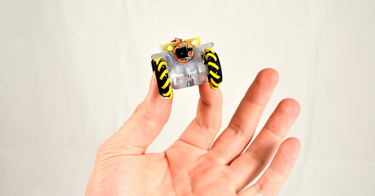
Honeybee Robotics is another robotics company with inspection robots. They have been in business since 1983 and active in Space, Defence, Medical, and Oil/Gas industries. From the website, it seems that they have been very instrumental (pun?) in working with space exploration robotics, specifically the mars rovers. Most recently, the Phoenix drilling robot probe. For inspection robotics, they do not seem to have as much to offer, but you have the love the cute little (tiny) pipe crawling camera platforms.


Honeybee robotics magnetic Mecanum wheel technology

Honeybee Robotics camera pipe inspector
The pipe inspection robot is adorable, but I am not sure how well those wheels will be able to pull a cable load. The metal chassis does look very rugged. Inuktun Robotics - now part of Eddify is the maker of the Versitrax track system for inspection robotics. I have written about Inuktun in the past, as they have a very modular systems approach to their robotics.  Their track system is most impressive in shape and duty cycle.  (I am sure it has a nice price tag to go with it ;) the versitrax system was the inspiration for my design of the Wild Weasel.


Versatrax by Inuktun, now part of Eddify

Versitrax modular track by - Inuktun


GE Inspection Robotics - probably the market leader? I don't know for sure. But, I do know that GE is a top player in any industry the participate in. As a leader in power systems, they would have a strong need to provide inspection robotics for pipelines, boilers, crackers, etc.  The Inspection Robotics division is HQ in Zurich. They seemed to have acquired a number of robotics and software companies and are working to incorporate their technologies together. This is very typical of a large industrial player that can grow by acquiring innovative tech capabilities. (I am not knocking on the engineers that made these fine technologies!)
The Bike platform is one of their compact inspectors with strong magnetic wheels and mobilies technologies. It can drive/cross over a 90 degree corner!


GE Inspection Robotics - Bike Platform

Robot business opportunity, eh?  On a little more along the lines of small business, there are many small companies that will custom build inspection (and tactical) robots for you.  Here is one I recently found, that is located in the US state of North Carolina.
SuperDroid Robots  They specialize in their own custom built robots. Prices range from a few thousand USD to tens of thousands USD.  Check out their site, they have a lot of unique builds and many custom "fun" robots.


SuperDroid "RealCow Robotic System" - probably their most absurd robot (cowbot?)
I highly recommend checking out the site, everytime I go their, I find new robots that they have built. They are quickly becoming a favorite site, even as they have a tendency toward 'tactical'  ;)

speaking of tactical robots for warfighters...

DARPA's grand subterranean challenge - DARPAs grand challenge seems to be moving long.  They have recently completed stage 2 of the challenge.


DARPAs SubT Tunnel Challenge

Here is a great article by Popular Mechanics about the results of the DARPA Subterranean Challenge and the man-made Tunnel Circuit.  I think the impact of this will either be on the receiving end of lidar options, or it could spurn additional research in the Lidar/SLAM aspects of robotic development.  If you read the article, keep an eye out for the "robot with robots", this is one of my favorite themes for future robot explorations!

On the Software side of Robots
There have been a lot of improvements to software systems that will operate and control the robots of the future.  Many of these are open projects, that provide tools for 'the rest of us' to use in our hobbies and businesses.  Some of the most basic, are tools like the Robot Operating System (ROS) and simulators such as Gazebo. I would like to focus a little more on one aspect that will be required for Autonomous robots - Computer visions.  Specifially Computer vision that will be used for simultaneous localization and mapping (SLAM)

OpenCV is leading the way for computer vision with many libraries and easy to use.
openMVG uses multiple images and views to perform photogramy, or constructing the 3D space from graphical images.

With the strong focus by the industry on self driving cars there will be significant enhancements in lidar technology. This should lead to reduced cost for the sensors, and perhaps the processing being moved to a chip to provide direct sensor measurements to the robots SLAM routines.

Ambarella - Computer Vision on a chip, has a new robotics platform and partnership with Amazon. they started their business with video processing chips, but pivoted to providing CV on a chip. This is similar to the open source project of OpenCV (?).  At any rate, this is the types of innovations that will be coming in the next years. Many of the open AI type processing necessary for robotics will be moving to fast implementations on a chip.  (you can also think of this similar to GPUs being broken out from code to a chip).
they will need to work on their messaging a bit, their website states:  
Our intelligent video devices use face detection, analytics, and multi-object CNN classification to enhance security in businesses and homes, without the need for the cloud.
This might be contrary to the interest of their new partner, Amazon.  And a final note about Ambarella, as concerns over our society becoming more and more a surveillance state, this example from their advertising could be interpreted in poor taste:
Is surveillance becoming the new norm?


So, What (else) to Watch in 2020?

Will Amazon have any success in aligning their robotic offerings with these many disparate companies which do their own processing. 

As Boston Dynamics goes comercial, will there be a 'trough of disillusionment' (from the Gartner Hype Cycle) as it applies to robotic dog platforms?  It is a remote observation platform, that can walk in all weather and surfaces. but with remote observation and (limited?) manipulation. Or will we find new use cases that make it a viable, value added, platform.
Boston Dynamics - An Android and his Dog

As an obvious result of the Spot Mini, we have seen many new quadruped robots. All of these knock-offs (and I mean that in a good way) seem to have exact same capabilities and servo placements etc. It is my hope that we quickly move on from this and start to see some truly innovative approaches to robotics, after all they do not have to look like dogs or humans. They just need to be able to perform. This is evident in BDs third robot, Handle, that looks nothing like a human or dog. This robot is built entirely for function, it seems without any thought of form. If anything it looks like a very awkward bird, ok now I am doing the anima-morphing.

Boston Dynamics - Handle

Future?
So, What Would Elon Musk Do? (#WWEMD?)  How would you build your robot business?

Actually, I would not be surprised to hear that SpaceX is thinking about roving robotics. After all, the Falcon 9 is a robot ship (?).  But most of all Space exploration is going to require A LOT of new autonomous robots.

Saturday, April 6, 2019

Wild Weasel - Tracked Robot (#3)

I have just posted a YouTube Video of the assembly of the Wild Weasel track.  You can find it here:


Wild Weasel a completely 3D printed Tracked Robot.  I wanted to build a tracked robot, due to their stability, and at the same time use some motors that I had recovered from recycled printers.

The project went very smoothly, a lot of CAD work was need to design the treads, chassis, and gears used.  The robot uses a Raspberry Pi and an L298N motor driver. This was my first time to use a Tallent Cell power bank, which provides 12V and 5V power - great for RPI and the motors.

Saturday, March 2, 2019

Wild Weasel - tracked robot (#2)


The first build of the Wild Weasel tracked robot seems to be working well.


Wild Weasel Tracks - in Robot configuration
Here is a video from back in early build, where I first tested out the track.  The track is using two white gears that are from the recycled printer. I went on to recreate these and printing a duplicate set for the second track.  This involved counting the teeth and height and angle of the gears.  Here is a video from my YouTube channel:


As you can see from the video, it is very energetic with 12v of "shore" (mains plug) power. It was running all around my desk, especially as it had no frame besides for the track unit itself - as designed!! ;)

I have since added the Chassis frame consisting of modular units:  a battery bay, a controller bay, and the initial sensor platform.  The robot is fitted out with a tallent cell 12v/5v battery, Raspberry Pi, L298N motor driver, Logitech 920C camera, and USB speakers.


If you would like to drive the robot remotely...  !!  go to LetsRobot.tv and it might be available.  I try to put it online using my TotallyNotEvilRobotArmy stream on LetsRobot.tv.  You can find it here:  TNE-RobotArmy WildWeasel

LetsRobot.tv controls for Wild Weasel (type in chat to speak

Ready to go!
Wild Weasel in LetsRobot Configuration (with lance!)
Learnings and Next Steps:

After some time spent with users operating the Wild Weasel on LetsRobot.tv, there are some learnings. LR is a great way to test out design, the robot gets a lot of (sometimes hard) use.  

  • My clever design for locking the module connections does not work.  the 3D printed pin and loops shear off under force. a better solution is to use metal nails perhaps.
  • One of the motor stalls much earlier than the other. This may be due to low power from the battery. I will test this further.  The impact is that the robot will not drive straight
  • The MQTT client is reading duplicate values sent from the streaming site. I will update the code to ignore long strings of the same command.
  • Need a better override at the MQTT level. perhaps a second command channel that will allow me to flush the stream from the other channels.


Anti-Collision detection
Most important, I will be adding an Anti-collision code to the motor controller. I will be using an HC-SR04 ultrasonic distance sensor to determine if the robot is against a wall or other object. I believe the best interface will be just to ignore commands that would try to continue to drive into the obstacle.  more details on this to come.


Saturday, February 9, 2019

Wild Weasel - tracked robot (#1)

I have an interest in building and designing out a tracked robot... for some reason. :)  

Tracked robots have static stability, and typically should not get 'stuck' on terrain the way wheeled robots do. Also, you can build, drive, and steer a tracked robot with only 2 motors. The downside of the design is that to turn, they have to 'skid' or slide.

I wanted to design a track system that will be modular and can be combined with other tracks and platforms to easily create new robots. I really like the modular designs of the Intukun pipe inspectors robots. Their mini-track crawler is an impressive piece of crawling hardware. Of course, I wanted to build one like this too.
MiniTrac (80mm x 100mm x 400mm) - by Intukun

The other design influence was closer to the Maker space. On Thingiverse, I found a great design of a robot tank by Tim Clark, 
MR6 - Mini Prototyping Tank Robot. Tim had obviously put a lot of thought into this design. This robot is at least his third design variant on crawling robots. Being his latest model, it probably has the most learnings. 

I really liked the skateboard bearings he is using, as well as the track design, and the various layers of support frame. Although, I am still not sure what is the advantage of raised cog/sprocket to form a triangle.  I did not use his design, except for influence - I needed to have the design in OpenSCAD, and he did not provide source files openly.
MR6 - by Tim Clark


I set out to design my own tracked crawling robot using ideas from both of these designs. In addition, I wanted to re-use 12V motors that I have harvested from old printers.


Track, Sprocket, and Motors -- Ready for Design!

Design Concepts


I want the motor to be inside of the treads, so that there is no axel crossing between a motor and the gears, thus raising the ground height of the robot frame.  Only the motor power wires and the mounting frame will need to go on to the track module.  Thus the height dimension of the unit will be dependent on the motor size and clearance of the treads and sprockets.


(Red) Motor between two sprockets, creating a contained track modual.

the width of the treads has to account for the width of the motor. This affects the width of the sprocket/cog.  The sprocket will contain a 22x7mm skateboard bearing.  So, ultimately the sprocket is dependent on the bearing size, and the tread is dependent on the sprocket.


Frame to hold the motor and sprockets

The length of the track would be dependent on the sprocket size, motor size, and amount of gear reduction needed between the motor and the drive sprocket.  This value had to be determined in a few design iterations. Also at play the size of the gears and the size of the sprocket are closely coupled. In my build process I needed to add size to the sprocket to account for the larger gears I needed.

Frame and Gears to drive the treads

The sprocket size was increased, to provide more clearance to the motor and gears. Since the sprocket gear tooth size is directly linked to the tread size, increasing the sprocket, but keeping the tooth size, meant that I needed an additional tooth on the sprocket.  Thus in a design iteration, changed the sprocket from 12 teeth to 13 teeth.  This very subtil change has impact on the rotational angle location on the sprocket disc. 

Size of the sprocket determine number of teeth in Sprocket and Tread size

Tread design

I examined Tim Clark's treads very closely. I also examined the changes he made from earlier designs to later ones. The result I saw was from early to later designed the length (size of step) of each tread was getting smaller and smaller.  This result in a more fluid chain of treads.


Wild Weasel - Tread Segment
To keep the build process simple, I am using small nails that slide through the Tread Segments to lock them together.

Gear Design

The gears used to transfer the torque from the 12v printer motors to the sprockets had to be carefully designed and fitted.  The motor has a high speed and needed to be stepped down in a compact space.
I experimented with gears reused from old printers.  the common design is a large top gear connected to a smaller gear on the same axis.  This provides a method to reduce the rotation speed for each gear step.
The motors had diagonal toothed gears already on them.  I used a open source gear library in OpenSCAD to design the gears.  Using more fine settings on the 3D Printer produced incredible results.

OpenSCAD library by Dr Jörg Janssen, Getriebe.scad.  I highly recommend this library, although it is in German. (don't let that scare you! ;)
One gear of 4 used in the design.

Final Design


Interestingly, building laterally symmetrical (no upside, downside) means you do not need to have a left or right side. the unit can be flipped or rotated to either side of the robot. By making two copies, I can rotate one tread around to have the symmetrical pair, without having to have a second design.


Track Modual

Here is assembly construction of the first robot.
Wild Weasel tracked Robot Chassis - OpenSCAD
Here is the first print made of the robot, complete with parts.  Completely 3D printed.
Printed Design - Wild Weasel Tracks and Robot