Showing posts with label Exploring Robots. Show all posts

Wednesday, June 24, 2026

The Ferret - Tunnel Exploring Robot (#1)

TNERA - The Ferret Robot - AI Concept Art

Introduction

I always had a dream in the back of my head about having a robot to go into tiny spaces that I could not. To go down the proverbial rabbit hole and see what is there. This is my goal, to build exploring robots. Even ones that could be recast as pipe-inspection robots. 

Sounded to me like it would be a good weekend project, it also sounded like a good 'new' project that I could test out the capabiltities of using the current AI tools to help build the components. It would be a good test to see how they have improved in the last year. 

So, down the rabbit hole we go! Chasing the AI white rabbit!

Like it or not, We are living in a moment in time in which AI has created a time of software abundance. It is now far easier for individuals to create complex new software with ease. There’s a growing claim, a belief, that "Now anyone, can build anything". Many software Makers are doing just that: they are going back to previous projects that were to onerous to build in the past, and now building them.  

Can this be true for robotics projects as well?

Robotics has always been one of those domains that resists simplification. It is a heavy concentration of software, firmware, electronics, and mechanical design, all interacting in ways that tend to create complexity instead of removing it. Historically, that complexity has been a barrier for automated tools, it also makes it fantastically more interestings.

So this project—The Ferret—is my attempt to explore whether modern AI tools can meaningfully compress that complexity.

The Idea: A Burrow-Exploring Robot

Abandoned Burrow Hole - to be explored

I’ve had this idea for years: a small robot that can crawl into spaces people can’t—burrows, holes, confined environments—and explore them remotely.

To do this, I need something narrow. Cylindrical. Tracked.

A robot that can push forward into an unknown space with a camera and light, acting as a remote presence where a human simply can’t go.

The Core Challenge: Does current AI help here?

Any robotics project sits at the intersection of three domains:

  • Firmware - software that runs on the device
  • Electronics - how components are wired and powered
  • Mechanical design - what the robot physically exists as

AI is clearly strong in firmware and all software development. This part has already become trivial with early 2026 LLMs. Write a good prompt on what you want the firmware to do, and the AI agents can write it for you in minutes.

But how can AI be used to Generate usable 3D printable CAD? used to help design mechanical systems? or provide meaningful assistance with circuitry? This is the real test.

Starting Mechanical Design

The process started not in CAD, but in conversation. Before building anything, I worked with an AI session to:

  1. Define constraints 
  2. Explore design options 
  3. Clarify tradeoffs 
  4. Generate prompts that would later drive development

This turned out to be a useful pattern: design through dialogue first, implementation second.

OpenSCAD and the Nose Cone

I use OpenSCAD for CAD work. It is openSource, and completely codified, which makes it easy for an LLM to write the design in.

Historically, AI has been… really bad at it. Almost unusable.

So I started manually, designing the front of the robot—a nose cone. I knew what I wanted geometrically, but not what to call it. So I asked Gemini Flash. It identified the shape as an elongated ellipsoid, common in aerodynamic designs, and even generated OpenSCAD code for it.  I pasted it in.

It worked immediately.

That was the first signal that something had changed.

Building the Tracks

With that success, I quickly moved over to the design of the caterpillar tracks. This wasn’t my first time building tracked systems (see the Wild Weasel). I had a good mental model of how it should work.  The AI suggested I use Linked track system, where there are two distinct parts like a bicycle chain or chain on a chainsaw. There is some benefit of the cog locking of that method. However, I would prefer a universal (continuous) track system based on preference and past experience. The continuous track uses a single universal track tread that is much easier to print in mass.

The Ferret Robot - Single Track Piece CAD design

The Ferret Robot - Track Pieces in line CAD design

I spent about an hour designing the first track segment manually. It worked well.  a base tread, with a hinge that I could insert small metal rods into. Then, I asked GPT to generate a similar design based on my comments. The initial CAD code output was not very useful. However, I uploaded my design as a rough guide not fully spec'd out, and the AI was able to match and complete the track accurately. The AI was not perfect 'from scratch' like the nose cone, but it was highly effective when guided. 

The Hard Part: Sprockets

Honestly, tracks are easy compared to sprockets. Sprockets are like gears, but they pull chains or track treads instead of meshing with other gears. The geometry of a sprocket is very different to a gear. To work correctly, sprockets require: precise tooth geometry, correct spacing, proper engagement with the track, provide alignment, and support tolerances. Designing a working sprocket is tedious and error-prone.  Another good test of the AI!

The Ferret Robot - Sprocket CAD design

From above, I input the track design to GPT and provided a vague prompt to design a sprocket to fit the track. It did it in less than a minute. The AI generated the geometry, selected a tooth count, and calculated spacing and the included offsets. The design looked impressive, I added an axel and printed it to test.

Again, I found that the design didn’t work perfectly the first time—but it was close. It is not untypical in sprocket design to iterate through small variations to get the right fit and tolerances. This time, instead of manually editing the openSCAD code, I simply described the problem in plain language and let the AI adjust the design. It took five iterations to get a perfect fit. The only parameter I had to tune was offset, which is exactly what you’d expect in manual iteration anyway.

The Ferret Robot - Sprocket sizing iterations. Final on Right
Tensioner and frame on top with sprocket
Track tread length on bottom 

The key difference: I never had to reason about sprocket geometry directly. The sprocket design was custom, not a library. the AI built the hub and teeth on its own. That’s a new skilled behavior to me, the AI has come a long way!

Initial mechanical design assessment

At this stage, I was pretty happy. The Nose Cone was pretty easy to "generate", the track design went better than expected. It took me signifcantly less interations to perfect (and it printed very nicely too). most of that design came from the Wild Weasel, the AI quickly parameterized it. And finally the sprocket was trivial, next to the typical effort to design and adjust. AI can now participate meaningfully in mechanical design—especially when guided. 

Ferret Robot: Original motor idea
pre-V1: nose cone, ESP32-CAM, tracks, sprocket, battery, and motor driver.

So, I was feeling pretty happy. Happily building and happily ignoring some of the more obvious warnings I was getting feedback on from the AI... That is the next story!

Saturday, May 30, 2026

Robots in the Wild: Deep Trekker - ROV

Spotted the other day: a robot in the Wild!  A field crew from H2O Drones B.V. running a well-used Deep Trekker REVOLUTION ROV through an underground passage carrying the north branch of the Düssel river (Nördliche Düssel).

H2O Drones - Deep Trekker ROV - exploring the Düssel

I was not expecting to see a robot crew working out of the back of their van on my walk. Bright yellow tether cables were looped across the pavement, a scratched-up robot perched beside a manhole, and the crew was preparing to send it on a mission into a dark, flooded tunnel under the city. This was no prototype lab machine, not a trade-show robot, but a working robot covered in the scratches, scuffs, residue, and improvised mounts that come from doing real inspection work.

The mission was to scan and search roughly 500 meters of underground river passage. Like many European cities, Düsseldorf has built over the majority of the waterways that feed into the larger rivers. Today the Düssel was running low after the recent heat dome and lack of rainfall, which likely made access easier, but the tunnel still looked like the kind of confined, dangerous, flooded, low-visibility environment where sending a robot is much better than sending a person.

Deep Trekker - Revolution ROV - well used!

The ROV itself looked heavily used, this was a working robot in all respects. The base platform was a Deep Trekker REVOLUTION, I was told - the logos had all been worn off! The ROV already has a primary lighting, camera, and sonar. This robot was fitted with additional equipment bolted to the top frame. The extra hardware looked like auxiliary inspection gear, a large flood light and a camera, or other optical sensing equipment for navigating and documenting the tunnel. Perhaps you can identify the additional sensor, leave a comment.

Additional Sensors bolted to the top of the ROV

This was a real working robot, that is what made it such a good “robots in the wild” sighting. The robot was not a camera drone taking pictures of the city. It was doing infrastructure work: going where people do not easily fit, doing real inspection work. And to me, the exciting part of exploring a hidden underground space - A small robot, a long cable, a dark river tunnel, and 500 meters of the unknown ahead. Very cool to stumble across.


P.S. The crew from H2O Drones were professional and very friendly. They obviously loved their job. When asked what was the most interesting thing they experienced doing inspections, they said "finding a beaver!" 

Monday, May 5, 2025

PolyMap & MinOne - MinOne gets Log-Odds (#5)

Improving Minone and PolyMap with Log-Odds

I have recently upgraded Minone and the PolyMap mapping system, focusing particularly on enhancing our use of a Single Ultrasonic Sensor. While the sensor hardware remains unchanged, introducing the concept of "log-odds" has significantly reduced the impact of noise and false readings, making our maps clearer and more accurate.

What are Log-Odds? (Explained Simply)

Imagine you're guessing whether it will rain today. You might say there's a 50/50 chance—that's "even odds." Now, suppose new clouds roll in, and your chances become "likely" rain, maybe 75%. Each time you get new information, your confidence about rain happening or not happening changes.

Log-odds is just a special way of keeping track of these changing guesses. It turns probability—the chance something is true—into a number that's easier to update quickly. Positive log-odds numbers mean "more likely," negative log-odds numbers mean "less likely," and zero means completely uncertain.

Occupancy Grids - Binary vs Log-Odds

Applying Log-Odds in PolyMap's Occupancy Grids

In mapping, especially with sensors like the ultrasonic sensor used in Minone, each measurement tells us something about whether space is empty or occupied. However, sensors aren't perfect; sometimes they say there's something there when there isn't (false positive) or fail to detect something that really is there (false negative).

Using log-odds, The system doesn't just accept each measurement blindly. Instead, it builds confidence over multiple readings. Every time the ultrasonic sensor scans an area:

  • A positive reading increases the log-odds, suggesting the area might be occupied.

  • A negative reading decreases the log-odds, suggesting the area is likely empty.

Over time, genuine obstacles build a strong positive score, clearly marking them as occupied on our map. Meanwhile, random noise, causing occasional false readings, doesn't build enough consistent evidence, so these points eventually fade away, staying neutral or negative.

This approach makes the PolyMap occupancy grids more reliable and accurate, greatly improving how robots navigate and interact with their surroundings.

A Deeper Look into the Math of Log-Odds

Log-odds translate probabilities from their natural scale (0 to 1) into a 'logarithmic space,' which makes it easier and computationally more efficient to combine multiple pieces of evidence. In probability space, values close to 0 or 1 become increasingly difficult to update because small incremental changes can have disproportionate effects. By shifting to log-space, updating becomes straightforward additions and subtractions, maintaining precision across multiple sensor updates.

When updating log-odds:

  • Positive evidence: If our sensor indicates an obstacle, we add a fixed positive log-odds increment, quickly shifting the belief towards occupied.

  • Negative evidence: If the sensor suggests no obstacle, we subtract a smaller fixed increment, slowly shifting back towards uncertainty or free space.

To prevent numerical instability, clamps are applied to the log-odds values. These clamps set upper and lower bounds, ensuring values remain within practical limits, preventing overruns that could result in overly confident (extreme) occupancy or vacancy assertions.

This additive and controlled adjustment property allows for quick, stable, and efficient updating, even with multiple sensor readings, greatly enhancing computational efficiency and clarity in interpreting sensor data.

Practical Results from PolyMap

Since implementing log-odds in PolyMap, there are substantial improvements:

  • Reduction of False Negatives: Previously, true obstacles were sometimes overlooked due to sensor noise and rapid changes in sensor readings. By quickly reinforcing log-odds with positive detections and slowly decreasing with negative readings, our system now reliably maintains the presence of real obstacles, significantly reducing false negatives.

  • Clearer Obstacle Identification: True obstacles are now distinctly recognized after several confirmations, making navigation decisions safer and more confident.

These practical outcomes directly enhance robot efficiency, reducing navigation errors and improving path planning capabilities.

Future Improvements and Considerations

Moving forward, I will be exploring additional enhancements to further refine occupancy grid accuracy:

A key challenge is tackling the ultrasonic sensor's tendency to miss obstacles when pulses reflect at oblique angles, effectively making these obstacles invisible. This issue arises because the sensor’s sound pulse can deflect away, failing to return the echo needed for detection. To address this, I am considering several options:

  • Sensor Fusion: Integrating data from multiple sensor types, such as infrared, alongside our ultrasonic sensor to build an even more accurate picture.

  • Multi-Angle Sensors: Using multiple ultrasonic sensors at different angles to ensure obstacles are detected from various perspectives.

  • Adaptive Orientation: Dynamically adjusting the sensor's orientation or positioning to better capture reflections from challenging angles.

  • Enhanced Signal Processing: Implementing advanced signal analysis techniques to better distinguish weak echoes or indirect reflections.

I believe these improvements will further strengthen PolyMap's reliability, making the robot even smarter and more autonomous. 

Sunday, April 27, 2025

PolyMap & Minone: First Test Results (#4)

Simple SLAM Robot: Initial Tests with PolyMap and Minone

Both the PolyMap mapping platform and the Minone robot have reached a level of functionality sufficient for their initial tests together. The early results are exciting, though clearly revealing room for improvement—exactly as anticipated!

Here's a video capturing these very first tests. Having this visual documentation will greatly help us track the robot's progression as we refine and improve the SLAM capabilities.

Overview of the First SLAM Tests

These initial tests show how well the mapping system, PolyMap, works together with Minone, a very minimal robot platform that is built around an ESP32 microcontroller. Minone, equipped with only a single ultrasonic sensor, navigated a confined hallway environment. All communication between the robot and the mapping software was successfully managed via MQTT, demonstrating effective real-time integration.

Minone, alone in the hallway.


In this test setup, Minone was in a hallway out of my vision. My phone was recording its movement. I sat in an adjacent room behind the door and was instructing the robot through the visualization. Commands were sent using MQTT to the robot and telemetry and map data was returned as previously discussed. In this test, I did have the reassurance that it was working, as I could hear the motor movement down the hallway.

Mapping Process and Key Observations

The PolyMap visualization provided live feedback during the tests with telemetry and maps. On the map you can see:

  • Robot position was clearly indicated in orange.

  • Obstacles detected by the ultrasonic sensor appeared in red.

  • Unexplored areas remained marked in black.

  • Telemetry shows the Pose (X, Y, Θ) and state: Manual

PolyMap Viz April 2025 (Totally Not Evil Robot Army)

The visualization effectively demonstrated the system's ability to build a cohesive map from successive sensor readings. However, the tests quickly highlighted significant limitations associated with relying on a single ultrasonic sensor:

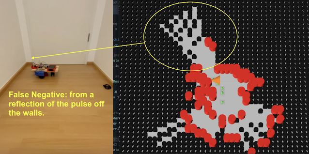
  • False negatives: The sensor occasionally failed to detect obstacles, particularly when encountering oblique angles. The pulsed ultrasonic signal reflects off the surface and does not return to the sensor, the device times out waiting, and returns a long distance (in this case greater than 170cm)

  • False positives: There were numerous instances of the sensor incorrectly registering obstacles due to noise and sensor inaccuracies. This could be due to echos, but otherwise indeterminate (for me at this time).

Minone, False Neg due to Reflection in corner.

These limitations underscore a common challenge when using ultrasonic distance sensors. In simple SLAM test, there were no special filter applied or sensor data management used. This is a clear direction for improvement in the next code iteration.

Initial Conclusions and Immediate Next Steps

The primary next step is addressing the significant number of false positive and negative readings produced by the ultrasonic sensor. To tackle this challenge, the mapping algorithm will transition from a basic binary representation (occupied/free) to a probabilistic occupancy grid, employing the log-odds methodology. This approach should significantly reduce the influence of sensor inaccuracies by statistically weighting sensor readings over time.

Looking Ahead: Introducing Mintwo and Exploring Swarms

Future development plans include building an upgraded version of Minone: the Mintwo robot (?!?). This iteration will be enhanced by incorporating multiple IR time-of-flight sensors, dramatically enriching the data quality and robustness. The improved sensory capability of Mintwo will not only enhance individual robot performance but also lay the foundational work for exploring coordinated behaviors and swarm robotics, leveraging PolyMap’s scalable and distributed architecture.

Stay tuned as we continue to iterate and enhance both the PolyMap platform and our expanding army, ehr.. family of robots!

Sunday, April 13, 2025

Minone – Getting the MV#Robot to Stable (#3)

Minone – Getting the MV#Robot to Stable (#3)

It's been a busy stretch since the last update! Many improvements, refactoring, debugging, and learning sessions have pushed the Minone MV#Robot toward a more stable and robust platform.

Code: Structure and States

Most of the recent effort has been dedicated to fleshing out software needed for remote operation. The robot's codebase has significantly expanded, particularly around the command structure. I've implemented a state model to handle essential high-level states:

  • Standby: Robot awaits commands—especially useful after a reboot, allowing manual verification before resuming tasks.

  • Manual: Direct control, crucial for immediate testing and remote operations.

  • Autonomous: Fully independent operation. Future enhancements will include advanced exploration strategies, frontier search, and swarm coordination.

  • Pause: Temporary halt; currently, the robot resumes directly into Autonomous mode.

  • Error: Safety state activated by unexpected issues.

High-level state changes are now managed via an MQTT subscriber, enabling remote state-level commands. In Manual mode, the MQTT listener also accepts individual task commands for immediate execution.

To efficiently handle robot actions ("tasks"), I developed wrapper code that allows manual triggering for debugging flexibility. Additionally, during Autonomous mode, the Robot's Agent autonomously generates tasks, utilizing the same task infrastructure.

Precise Movement Challenges

One aspect differentiating a true robot from a toy or simple remote-controlled device is the ability to move precisely. For mapping and SLAM purposes, it is crucial to know exactly where the robot is and its pose. To understand how much a motor has turned, an encoder is used to 'count' the amount of rotation. Minone uses encoders that are built into recycled Roomba wheel modules I am using. Knowing the number of pulses per rotation and wheel dimensions allows precise odometry calculations—determining how far the robot moves or rotates.

Initially, Minone exhibited incorrect odometry during turns. Calculations seemed accurate—asking to move 10cm resulted in software reports of 10cm—but the physical movement was actually 20cm. This discrepancy first appeared in rotation measurements, which were exactly half the physical result. At first, I assumed calculation errors were related to the complexity of the turn calcuation. The wheels are rotating in opposite directions and you must factor in wheelbase dimensions. A quick patch improved turn precision slightly, but the underlying movement issues remained.

Digging deeper revealed encoder pulse counts were half the expected values. Although the very specific 508.5 pulses per rotation was correct, I initially misunderstood that this value included both rising and falling edges of the encoder's square-wave pulse. A small adjustment resolved this completely:

// --- Encoder Setup ---
void setupEncoders() {
  pinMode(LEFT_ENCODER_PIN, INPUT_PULLUP);
  pinMode(RIGHT_ENCODER_PIN, INPUT_PULLUP);
  attachInterrupt(digitalPinToInterrupt(LEFT_ENCODER_PIN), leftEncoderISR, CHANGE);
  attachInterrupt(digitalPinToInterrupt(RIGHT_ENCODER_PIN), rightEncoderISR, CHANGE);
}

Switching the interrupt trigger from 'RISE' to 'CHANGE' allowed counting both edges. Problem solved! Recognizing this resolved earlier incorrect adjustments, making robot turns and movements significantly more accurate—not perfect yet, but sufficient for this prototype stage.

A cautionary note on AI-assisted coding: Unfortunately, my AI coding companion missed this nuance, underscoring the continued need to have some knowledge of what you are working with, both in code and hardware. The AI repeatedly suggested using 'RISE,' which cost significant debugging time. Only through examining code from other experienced developers—a big shout out to Bill at DroneBot Workshop—did I discover the proper approach.

Coordinate Systems & Rotational Model

Choosing a coordinate system for your robot is critical, impacting navigation, mapping, and visualization. Coordinate systems aren't always the simple math we learned in high school (traditional X/Y axes). You must consider the Z-axis for rotation and eventually 3D mapping, plus how your robot’s "frame of reference" relates to mapping standards reference. Surprisingly, industry standards differ significantly from basic Cartesian assumptions.

I selected a right-handed system (X-forward, Y-left, Z-up) for the robot frame, aligning with robotics conventions used in platforms like ROS. Positive yaw indicates counterclockwise (left) rotation, while negative yaw indicates clockwise (right) rotation. Though initially counter-intuitive, maintaining consistency across code and system interfaces is very important.

Downstream, the Map Manager and visualization components must translate these standards, especially when interfacing with game engines like Godot, which often uses a different convention.

Minone 11 APR 2025 - MV#Robot

Hardware Improvements

The prototype hardware has also been improved in this iteration. Adding a level shifter stabilized communication between components with different voltage domains. To safely power the ESP32 independently, I now directly use a clean 5V source from a power bank rather than the L298N's regulator.

Currently, the robot remains on a breadboard— a big messy rats nest of jumper wires. Future builds will transition to a safer proto-board with robust connectors for stability and better cable management, reducing risk of havoc from loose connections.

Demos: Seeing the Progress!

Here are short videos captured during the build process. The first demonstrates basic movement and scanning routines without intelligent decision-making:

The second video shows progress after foundational movements were implemented but before odometry corrections—movements rely on timing rather than accurate angle calculations. Since filming, accuracy has significantly improved!


Thanks for following along! The Minone MV#Robot journey continues—iterate, iterate, iterate!

Saturday, March 29, 2025

Minone - Starting the build (#2)

Early minone - TNERA MVP Robot

Minone Build Log #2: The Grind Begins

Minone is a Minimal Viable Robot, built as a prototype for my development of PolyMap, a multi-agent mapping system. It’s a bare-bones junkyard robot—scrapped components, an ESP32-S, and some basic electronics. And let me tell you—it’s fantastic for learning how the real physical world and the virtual one collide. And boy, does it grind.

Core Components:

  • ESP32-S dev board
  • L298N - motor driver
  • Scraped Roomba Motor Modules (with encoders)
  • HC-SR04 Ultrasonic Sensor
  • MG90 servo
  • and a 12V/5V power bank

Here is a highlevel schematic of how they are connected together:


Everything’s wired up pretty simply—and that’s where the real problems start. 😄

Voltage in and out: 3.3V vs 5V

The ESP32 runs at 3.3V logic, but nearly all my sensors are 5V devices. That means input signals need to be stepped down, which I’ve handled using voltage dividers. No big deal.

The trickier part? Outputs. The PWM signals that drive the servo, trigger the ultrasonic sensor, and control the motor driver are all a bit underpowered at 3.3V. Some devices tolerate this. The L298N? Not so much.

That means it’s time to level shift those outputs. A voltage divider doesn’t cut it here. I’ll be testing a proper level shifter soon to ensure robust 5V signaling.

PWM Resource Conflicts on the ESP32

One of the most valuable lessons so far: PWM timers and channels are limited and easily conflicted.

At first, I had a nice ultrasonic sweep working via the servo—classic radar style. But after I added the motor drivers and encoder logic, the servo went haywire. High-pitched whining, jittering, and eventually… nothing.

What happened?

Turns out, the servo and motor driver were fighting over the same PWM channels. The servo took channel 0 by default. The motor driver was hardcoded to use channels 0 and 1. This conflicted both the frequency (servo at 50Hz, motor at 5kHz) and the timer allocations.

My first fix: reorder the initializations to let the servo grab a channel first. This helped, but wasn’t enough.

The real fix: manually assign a separate timer and channel to the servo. I dedicated timer 1 / channel 2 for the servo just before attaching its pin. That separated its timing cleanly from the motors—and everything started playing nicely again.

It cost me a bit of time, but the lesson was well worth it: don’t assume PWM resources will sort themselves out.

The Mysterious Unbootable EPS32

When shifting to local (robot power), Minone just… refused to boot. No errors, no logs—just silence. After way too much head-scratching, I finally pulled out the multimeter and discovered the culprit: the L298N motor driver was holding GPIO 12 and 15 high on startup. Turns out, those pins are a bit picky—they must be low for the ESP32 to boot.

No amount of code, pull-downs, or wishful thinking could override the voltage being held by the motor driver’s enable pins. The only fix? Move those signals to different GPIOs. I ended up switching to GPIO 19 and 22, and just like that—boot restored.

Sometimes, it’s not a bug—it’s physics.

A note about "Vibe Coding"

Throughout the development of Minone (and PolyMap), I’ve leaned heavily on LLM-based AI to guide the process—something the industry is starting to call Vibe Coding. As many have noted, Vibe Coding is a fast way to build software that might otherwise be just out of reach. And honestly? I recommend it, but not for beginners to coding.  [Update: Vibe Coding now has negative connotations. What I recommend is using it as a tool, not over dependence on it.]

AI has helped me rapidly prototype, implement features, and solve specific technical challenges. But beware—it’s not all smooth sailing.

Where AI shines is in writing clean, functional code based on known patterns. It’s excellent at pulling in details, explaining APIs, and even suggesting optimizations. But it often struggles with the human side of development—especially incremental development, integrating features, and aligning with the developer’s mental model.

A big part of my time is still spent going back through generated code line-by-line, trying to understand what it’s doing and whether it matches what I need it to do.

There are also assumptions—sometimes wrong ones. For example, in my code, the AI assumed the encoders were infrared-based, when in reality they’re Hall effect sensors. It’s up to the developer to catch those mismatches and feed corrections back into the conversation. Once pointed out, the AI adjusts quickly, but it doesn’t ask enough questions up front to avoid such errors.

Another example: determining the number of pulses per revolution from these old Roomba motors. This spec isn’t widely documented, and the AI couldn’t give a definitive answer. I had to dig through old boards and obscure web forums to figure it out.

The takeaway? AI is an incredible tool—but the human still needs vision, intuition, and a working understanding of how systems should behave. We’re closer than ever, but not quite at full autopilot.

Incremental Robot Development: ✅ Turning left 

Here’s a quick one: I connected one of the motors directly to the battery—pure chaos, purely intentional. 😄

Sure, it was just to confirm the motor worked. But from a test-first, incremental development perspective? We can officially check off:

✅ Turning left.

Progress!

State of the Platform

Minone is now stable. The essentials—WiFi, MQTT, sensor reads, sweeps, motor movement, and encoder feedback—are all working together smoothly.

The platform’s ready for the next steps:

  • Fully Integrated into the Godot visualization
  • A much much more curious Robot Agent
  • Mapping the basement hallway - the Testing Goal

Sunday, March 16, 2025

PolyMap: Leveraging Godot for Visualization (#3)


Leveraging Godot for PolyMap Visualization

Introduction to PolyMap and Visualization Goals
PolyMap is my experimental platform exploring multi-agent, robotic swarm-based Simultaneous Localization and Mapping (SLAM) strategies for mapping real-world environments. Development has been incremental: starting with a simulation, robot agents, a mapping manager, and basic visualization. One key goal was to leverage existing technologies like game engines to rapidly create an operable system. Game engines also offer a natural interface to visualize the spatial data generated by the robots as they explore physical space—and it’s just really cool!


Why Godot?

Why use a game engine instead of existing tools like RViz? There’s no single answer. RViz and others are developed for the ROS environment and are reportedly easy to integrate with ROS, but I haven’t explored ROS yet. Possibly due to hardware constraints or concerns about getting locked into a specific architecture, I’ve chosen instead to learn the fundamentals of the (robot) science before adopting fully developed solutions. This is also exactly why I’m starting with a single ultrasonic sensor rather than a Lidar for spatial sensing. There is a vast amount of unbuilt software needed in this space, and I want to understand the basics before being embedded in one ecosystem. (A related question: is ROS becoming a walled garden?)

I chose Godot because it’s open source, has no license fees, and has a large community. It can render immersive 3D environments with advanced graphics and interactivity—features that would take far longer to build from scratch. This makes enhancements like zooming, panning, robot tracking, and detailed exploration straightforward. Overall, it’s a friendly platform for any maker stepping into games or 3D visualization. Plus, Thor from Pirate Software thinks "Godot is the Blender of game engines". 😉


Transitioning from Python to Godot
The original Python-based visualization tool was a solid proof-of-concept for displaying the global map and robot telemetry. As the project matured, I planned to try a game engine to overcome Python’s limitations in interactivity and feature expansion—where everything had to be built from scratch. 

Transitioning to Godot 4.4 opened new possibilities for a more fluid UI. Because PolyMap uses MQTT for distributed communication, multiple visualization clients can consume the same data. This architecture also means each component can be developed in the best language for its function: the simulation and map manager will stay in Python, while the robot agent code (currently Python) will move to C++ for real hardware deployment. 🤖

Here is a video showing the transition and new version:


Integrating MQTT Communications in Godot
A critical aspect of PolyMap is using MQTT for data exchange. Fortunately, people like Goatchurch paved the way by porting MQTT code into Godot. It was showcased at a Godot convention, and most importantly, their open-source work on GitHub allowed me to clone it. Within a short time, messages from my existing Python version appeared in Godot. Once the MQTT connections and message handling were in place, communications were solid, letting me focus on features and functionality.

In the prototype, there’s a connectivity dialog box where the user enters the server URL, port, user ID, and password. It also allows topic subscriptions and message publishing. In this setup, the visualization subscribes to global_map and telemetry topics. Currently, the entire 100×100 integer map is broadcast every second, alongside telemetry data from the robot agents.


Using Godot
One of the most exciting aspects of Godot is how easily you can configure screens and add new features. Godot is heavily object-oriented; everything is a Node with attributes and methods. It reminds me of early “thick client” GUI development (pre-Web, like Acius 4D). This is my first Godot project, so I’m still learning and deciding how much to configure in the editor versus coding in scripts. Right now, screen elements are configured in the editor, while global map rendering is done in code.

There is a learning curve to working with Godot, but I understand it is very similar to other game engines like Unity and Unreal engines. For me, it was natural to code with an AI (or two, or three) to help me quickly learn how Godot works. There are also good videos on YouTube as well such as this video. One issue I ran into was that many of the AIs did not know how Godot 4.4 had changed from earlier versions, there was a constant effort required to correct the AI when it was off hallucinating. 🙂

Building the first prototype had its challenges: positioning the camera to view the map, deciding where to place MQTT functions, and balancing performance between rendering each grid point individually or using a grid mesh. Once I got the hang of Godot, it was surprisingly simple to get the visualization working. Adding a mouse-wheel zoom took only five minutes. I’m excited to add more capabilities quickly!


Future Features
With the first iteration working, here’s what I’m planning next:

  • Persistent Map: I can choose between redrawing the global map each time, or making it more persistent and only updating changed elements as the are discovered by the robot.
  • Free Fly - Camera: I will change the primary camera and give the user the ability to 'free fly' over the map moving around the landscape discovered by the robots. 
  • Robot FPV: It should be possible to put a camera in each of the virtual robots, allowing the user to select the robot and view the 3D space from its perspective.

Looking ahead, I’m breaking out the map manager and robot agent code from the simulation, moving toward a distributed computing platform. This is a key step for migrating from simulation to real hardware. Stay tuned for more updates!

Saturday, March 1, 2025

Polymap: Mulit-Agent SLAM Simple Simulator (#2)

Multi-Agent SLAM! with Distributed Data Fusion and Frontier Searching


PolyMap is an experimental platform designed to explore Robotic Swarm–based Simultaneous Localization and Mapping (SLAM) strategies across both simulated and real-world environments. The mission is to harness distributed robotic sensor data, real-time MQTT communications, and advanced data fusion to develop robust, collaborative mapping environments that bridge virtual (systems) and the physical (machine) world.

Recent Work

Robust MQTT Communications & Security
The MQTT infrastructure now enables secure, real-time data exchange between robot agents and the Map Manager. With brokers, subscribers, and publishers designed to run on distributed platforms, the system is designed to scale smoothly to multiple robot agents. Integrating data from distributed sources has enhanced the completeness of the global maps.

PolyMap MQTT pipeline


Frontier Searching Implementation
I have integrated frontier searching techniques—drawing inspiration from Yamauci, 1997—to systematically prioritize and explore unknown regions of the map. This approach is central to refining our mapping strategy by dynamically guiding the system to areas that require further investigation.

Enhanced Visualization
The python visualization is now somewhat fully functional, offering a clear and dynamic representation of the evolving global map. Real-time updates provide immediate robot telemetry and map fusion data, ensuring that the state of the environment is always accurately reflected.

YouTube Video Demo
Here is a YouTube video showing PolyMap in action. You can see the simulated robots navigate in a virtual environment, exchange data via MQTT, and merge their local maps into a dynamic global view—all in real time. 


Current Challenges

Robot Agent Behavior
While our simulation demonstrates significant progress, the robot agents exhibit limited exploratory behavior and are challenging to fine-tune. They often get stuck in corners, a behavior likely influenced by the coarse resolution of the current scanning technology. This is a complete topic that I will expand on more in the future.

Polymap: going long on Frontiers

PolyMap: Robot Agent Exploration


Operational Mode Transitions

In the system, robots cycle through distinct operational states that define their behavior during navigation. These include:

  • Scan Mode: Actively gathering sensor data.
  • Idle Mode: Maintaining a standby state when no immediate action is required.
  • Obstruction Mode: Responding to detected obstacles.
  • Frontier Mode: Venturing into uncharted areas for further exploration.

While these states provide a structured approach to managing robot behavior, the transitions between them need further review and refinement. Enhancing these transitions is critical to achieving smoother performance and greater responsiveness during navigation.


Upcoming Developments

Enhanced Sensing
We are set to incorporate a 'radar-like scan' into both our simulation and physical platforms. This upgrade will augment the capabilities of our single ultrasonic sensor, providing richer, more detailed environmental data.

Physical Implementation – Meet MinOne
The physical build of “MinOne” is now underway. This robot will serve as the real-world counterpart to our simulation, enabling us to bridge virtual testing with tangible, hands-on experiments.

Next-Generation Visualization
In our continuous effort to improve user experience and performance, we are evaluating the Godot engine as a potential upgrade for our visualization tool, aiming to deliver a more immersive and high-performance display.

Further Enhancements
Moving forward, we will focus on fine-tuning robot behaviors and sensor parameters, as well as exploring additional sensor integrations to boost mapping fidelity. The goal remains to develop a scalable and robust platform for multi-agent SLAM exploration and discovery.


PolyMap's evolution is driven by a relentless passion for iterative improvement and DIY robotics innovation. This project is about building something tangible—each challenge overcome and every feature refined brings PolyMap closer to bridging the gap between simulation and reality and expanding the boundaries of collaborative robotic mapping.

Wednesday, February 19, 2025

Minone - Introduction of my MVP Robot for SLAM Exploration

Exploring Robots are cool. Robots that map their surroundings? Even cooler. But there’s a massive difference between slapping together a chassis and motors and actually building a robot that can autonomously explore and create a map of its environment. That’s the problem I’m setting out to tackle with Minone, my MVP (Minimum Viable Prototype) for an exploration-focused robot.

Minone - MVP for SLAM

Why Start Simple?

Most SLAM (Simultaneous Localization and Mapping) discussions dive straight into complex sensor suites—LiDAR, stereo cameras, high-end IMUs—but I’m deliberately taking the opposite approach. Instead of relying on fancy hardware, Minone is built to push the limits of simple sensors, starting with nothing more than an ultrasonic distance sensor (HC-SR04).

Why? Because understanding SLAM at its core—filtering noisy sensor data, estimating position, and reconstructing an environment—is much more valuable than just plugging in a high-end sensor and hoping for magic. I want to see how much useful data I can extract from the bare minimum before moving on to more advanced solutions.

A Scrap Yard Robot

In true MVP fashion, I built Minone from whatever I had lying around:

  • Chassis: The top of an old wine box. (Recycling counts as engineering, right?)
  • Motors: Two Roomba drive motors salvaged from an old unit.
  • Caster Wheel: From a trashed suitcase. (Turns out, old luggage makes for decent robot parts.)

It’s the ultimate scrap yard robot, which makes it easy to modify as I iterate. That’s already proving useful, since I’m starting to regret my choice of a trailing caster wheel—turning is fine, but the bot has a tendency to tip forward. A problem for Future Me to solve.

Electronics & Control

For brains and motion control, I’m using:

  • Microcontroller: ESP-32S
  • Motor Driver: L298N H-Bridge

This will be my first time working with an ESP-32S, so I’m looking forward to seeing how it handles real-time sensor inputs and motor control. The L298N should manage the Roomba motors' voltage needs just fine (in theory, at least).

The Underpowered Sensor Challenge

The HC-SR04 ultrasonic sensor is laughably weak for proper SLAM. It’s low-resolution, has a narrow field of view, and struggles with certain surfaces. But that’s exactly why I’m using it—I want to figure out how to make the most of bad data.

If I can extract meaningful spatial information from this absolute potato of a sensor, then adding better sensors later (IR, TOF, LiDAR) will only make the system stronger.

What’s Next?

With the basic hardware in place, the next steps will be:

  1. Getting Minone moving – Setting up basic motor control with the ESP-32S and L298N.
  2. Reading sensor data – Making sure the HC-SR04 is providing usable distance measurements.
  3. Starting simple SLAM tests – Even basic dead reckoning will be a good first step.

As I build and test, I’ll be refining Minone’s design—possibly rethinking that caster wheel before it faceplants one too many times.

Stay tuned for the next update! 🚀

Sunday, January 26, 2025

PolyMap: Introduction

PolyMap:
PolyMap is an experimental platform designed to explore Robotic Swarm–based Simultaneous Localization and Mapping (SLAM) strategies across both simulated and real-world environments. By combining lightweight simulation, MQTT-based communications, and emerging visualization techniques, PolyMap aims to offer an accessible yet robust toolkit in multi-robot collaboration and global mapping challenges.

Recent Progress: Building a Simple SLAM Simulator
I am pleased to share the latest milestones in developing a simple SLAM simulator under PolyMap. Over the past few weeks, I have laid the foundation for simulating robot behavior, visualizing real-time maps, and merging local maps into a unified global view. This work is an important step toward creating a versatile environment where multiple robots can collaboratively build and refine shared maps.

An early achievement in this release has been leveraging MQTT for robot-to-visualization communication. Each simulated robot transmits map updates through MQTT, which our visualization layer consolidates into a cohesive global map. I have also made headway on a basic search feature, an early step toward more sophisticated swarm coordination. Concurrently, I have improved the simulation architecture to ensure that incoming data and visualization processes run smoothly without blocking each other.

On the infrastructure side, I have established a basic development structure—not full CI/CD yet, but enough to keep things organized and maintain momentum. I have also incorporated early concurrency and event-handling mechanisms so that data flow and visual updates can occur in parallel. While there’s still much, much more to do, these accomplishments underline PolyMap’s potential to evolve into a compelling cooperative robotics exploration platform.

Next Steps and Future Directions
Looking ahead, I plan to explore using gaming engines to enhance our visualization capabilities, offering a more immersive and high-performance environment for simulating robot movements and interactions. Additionally, as the simulated framework matures, we’re setting our sights on integrating physical robots into the pipeline—bridging the gap between virtual testing and real-world application. By supporting both simulated and physical robot platforms, we hope to make PolyMap a flexible tool for multi-robot SLAM challenges. Stay tuned for more updates as the platform continues to evolve!

Here is a much more realistic screen capture of the actual 'early' simple simulation. ;)

Simple SLAM simulation

Monday, October 28, 2024

SLAM! - The Basics

[Note: this article is mostly a conversation I had with an AI. I likeed the output, so I am including it here. It may not be the most genuine of blog posts, but it is something I will refer back to, so I am sharing it with you as well.]

A Simple SLAM Simulation

SLAM, which stands for Simultaneous Localization and Mapping, is a critical concept in robotics, especially in autonomous systems where the robot must navigate through an unknown environment. Here’s a detailed breakdown of the basic components and methods involved in SLAM:

What is SLAM?

SLAM is the process by which a robot can:

1.  Map an Environment: Create a representation (usually a 2D or 3D map) of an unfamiliar area.

2.  Localize Itself: Determine its own position within that map, in real time.

SLAM is a solution to the "chicken and egg" problem of robotics: To map the environment, a robot needs to know where it is, but to know where it is, it needs a map. SLAM solves both tasks simultaneously.


Key Components of SLAM

1. Sensors: 

   - Lidar: Light Detection and Ranging (uses laser beams to measure distances).

   - Cameras: Visual or stereo cameras for Visual SLAM (VSLAM).

   - Ultrasonic Sensors: Simple but effective for obstacle detection.

   - IMUs (Inertial Measurement Units): Track orientation and movement changes.

   - Encoders: Simple but effective for tracking movement changes.


2. State Estimation: 

   - Pose: Position (x, y, z) and orientation (yaw, pitch, roll) are estimated continuously.

   - Common methods for estimating this are Kalman Filters or Particle Filters. For complex non-linear systems, the Extended Kalman Filter (EKF) or Unscented Kalman Filter (UKF) is often used.


3. Mapping:

   - The robot gathers spatial information about obstacles and free space.

   - Maps are usually grid-based (like occupancy grids) or feature-based. 

   - Occupancy Grid Mapping divides space into a grid of cells, marking each cell as occupied, free, or unknown.


4. Loop Closure: 

   - The robot must recognize a location it has visited before, called loop closure.

   - Without recognizing these loops, errors can accumulate, leading to an inaccurate map.

   - Visual features, like walls or landmarks, are often used for loop closure.


Mathematical Foundations

1. Probabilistic Approach:

   - SLAM typically involves Bayesian Estimation. A robot's state is represented as a probability distribution that evolves as new data arrives from the sensors.

   - Bayes Filters and Markov Localization are used to manage the uncertainty of sensor data and robot motion.


2. State-Space Representation:

   - The SLAM problem can be represented in terms of states and measurements, where states represent robot and feature positions and measurements represent distances and angles to landmarks.

   - The sensor model and motion model help update the robot’s understanding of the environment.


Approaches to SLAM

1. Kalman Filter-Based SLAM:

   - The Extended Kalman Filter (EKF) SLAM is one of the earliest methods.

   - It’s efficient but suffers from scalability issues in large environments due to the computational cost of updating a large covariance matrix.


2. Particle Filter-Based SLAM:

   - Also called Monte Carlo Localization (MCL).

   - Uses particles to represent possible positions of the robot. It’s highly robust for non-linear problems and can handle multi-modal distributions better than EKF.


3. Graph-Based SLAM:

   - The problem is represented as a graph, where nodes represent robot poses and landmarks, and edges represent constraints between them (from sensors).

   - After creating the graph, optimization is used to adjust all nodes, effectively minimizing the error in both localization and mapping.


4. Visual SLAM (VSLAM):

   - Uses cameras to detect visual landmarks. ORB-SLAM (Oriented FAST and Rotated BRIEF) is a popular implementation.

   - Visual SLAM can use either monocular or stereo cameras. Stereo cameras provide depth information directly, while monocular cameras infer depth using techniques like feature triangulation over time.


Mapping Techniques

1. Occupancy Grid Mapping:

   - The environment is divided into a discrete grid where each cell holds a probability of being occupied.

   - Updates occur using sensor data and can be represented by Bayes’ rule.

2. Feature-Based Mapping:

   - Instead of dividing space into grids, the system identifies key features or landmarks (corners, edges, unique patterns) and tracks them.

   - It’s computationally efficient in sparse environments.

3. Octomap (3D Occupancy Grid Mapping):

   - Uses octrees to create maps that efficiently represent 3D environments.


Challenges in SLAM

1. Sensor Noise: Every sensor has inherent noise that needs to be filtered out.

2. Motion Model Uncertainty: The real-world movements of robots have slippage and drift, leading to deviations between intended and actual motion.

3. Loop Closure Errors: If not correctly handled, identifying previously visited locations can lead to misaligned maps.

4. Scalability: Larger maps become computationally intensive, and optimizing these graphs for large environments requires sophisticated approaches.


Popular SLAM Frameworks and Libraries

1. GMapping: A well-known 2D SLAM algorithm using Particle Filters, often used with ROS (Robot Operating System).

2. Hector SLAM: Uses a Lidar and an IMU, known for high speed and low latency mapping in indoor environments.

3. Cartographer by Google: Supports both 2D and 3D SLAM, popular for its real-time mapping capabilities.

4. ORB-SLAM: A Visual SLAM library focusing on feature-based landmarks, very popular in robotics and augmented reality.


Use Cases in Robotics

1. Autonomous Vacuum Cleaners: These use SLAM to map a house layout and optimize cleaning routes while avoiding obstacles.

2. Delivery Robots: Like those used in Amazon warehouses, where they navigate autonomously through aisles and handle dynamic obstacles.

3. Drones: Drones often employ Visual SLAM to create maps of unknown environments for navigation and avoid collisions.

4. Self-Driving Cars: While more sophisticated, they often employ a form of SLAM to localize the vehicle and build environmental maps for path planning.

Ah...  These Use Cases are just the basic ones the AI can share, the low hanging fruit. The Use Cases are much, much, more expansive.  All robots and machines interacting in physical space will need some form of SLAM. Once the machine is localized and positions are known, then the applications of the sensors, manipulators, and motion can become effective. This is just the beginning, there are many applications that are yet to be realized or identified!


Advanced SLAM Topics to Explore

- Multi-Robot SLAM: Where a team of robots collaborates to create a common map.

- SLAM with Deep Learning: Incorporating neural networks to aid feature extraction and recognition, which can improve SLAM reliability, especially in challenging environments.

- SLAM in Dynamic Environments: Handling environments where objects are constantly in motion, requiring more sophisticated filtering to identify static versus dynamic features.


Conclusion

SLAM forms the backbone of autonomous navigation, providing a robot with the ability to understand and navigate in its environment. Whether using traditional Lidar-based approaches, visual methods, or newer graph-based optimization techniques, each approach has its own strengths and trade-offs depending on the application scenario.

Moving forward, I will be expanding my Simple SLAM! Simulator to explore the necessary components of SLAM.  My interest is (at-least!) two fold: 

1) The digitalization of physical space, fusing sensor data to observer and record that in our world that is difficult for humans to perceive in spectrum, space, and temporal dimensions.

2) Develop the concepts around Machine Perception of the physical world.