Showing posts with label Crappy Robots. Show all posts

Saturday, March 29, 2025

Minone - Starting the build (#2)

Early minone - TNERA MVP Robot

Minone Build Log #2: The Grind Begins

Minone is a Minimal Viable Robot, built as a prototype for my development of PolyMap, a multi-agent mapping system. It’s a bare-bones junkyard robot—scrapped components, an ESP32-S, and some basic electronics. And let me tell you—it’s fantastic for learning how the real physical world and the virtual one collide. And boy, does it grind.

Core Components:

  • ESP32-S dev board
  • L298N - motor driver
  • Scraped Roomba Motor Modules (with encoders)
  • HC-SR04 Ultrasonic Sensor
  • MG90 servo
  • and a 12V/5V power bank

Here is a highlevel schematic of how they are connected together:


Everything’s wired up pretty simply—and that’s where the real problems start. 😄

Voltage in and out: 3.3V vs 5V

The ESP32 runs at 3.3V logic, but nearly all my sensors are 5V devices. That means input signals need to be stepped down, which I’ve handled using voltage dividers. No big deal.

The trickier part? Outputs. The PWM signals that drive the servo, trigger the ultrasonic sensor, and control the motor driver are all a bit underpowered at 3.3V. Some devices tolerate this. The L298N? Not so much.

That means it’s time to level shift those outputs. A voltage divider doesn’t cut it here. I’ll be testing a proper level shifter soon to ensure robust 5V signaling.

PWM Resource Conflicts on the ESP32

One of the most valuable lessons so far: PWM timers and channels are limited and easily conflicted.

At first, I had a nice ultrasonic sweep working via the servo—classic radar style. But after I added the motor drivers and encoder logic, the servo went haywire. High-pitched whining, jittering, and eventually… nothing.

What happened?

Turns out, the servo and motor driver were fighting over the same PWM channels. The servo took channel 0 by default. The motor driver was hardcoded to use channels 0 and 1. This conflicted both the frequency (servo at 50Hz, motor at 5kHz) and the timer allocations.

My first fix: reorder the initializations to let the servo grab a channel first. This helped, but wasn’t enough.

The real fix: manually assign a separate timer and channel to the servo. I dedicated timer 1 / channel 2 for the servo just before attaching its pin. That separated its timing cleanly from the motors—and everything started playing nicely again.

It cost me a bit of time, but the lesson was well worth it: don’t assume PWM resources will sort themselves out.

The Mysterious Unbootable EPS32

When shifting to local (robot power), Minone just… refused to boot. No errors, no logs—just silence. After way too much head-scratching, I finally pulled out the multimeter and discovered the culprit: the L298N motor driver was holding GPIO 12 and 15 high on startup. Turns out, those pins are a bit picky—they must be low for the ESP32 to boot.

No amount of code, pull-downs, or wishful thinking could override the voltage being held by the motor driver’s enable pins. The only fix? Move those signals to different GPIOs. I ended up switching to GPIO 19 and 22, and just like that—boot restored.

Sometimes, it’s not a bug—it’s physics.

A note about "Vibe Coding"

Throughout the development of Minone (and PolyMap), I’ve leaned heavily on LLM-based AI to guide the process—something the industry is starting to call Vibe Coding. As many have noted, Vibe Coding is a fast way to build software that might otherwise be just out of reach. And honestly? I recommend it, but not for beginners to coding.  [Update: Vibe Coding now has negative connotations. What I recommend is using it as a tool, not over dependence on it.]

AI has helped me rapidly prototype, implement features, and solve specific technical challenges. But beware—it’s not all smooth sailing.

Where AI shines is in writing clean, functional code based on known patterns. It’s excellent at pulling in details, explaining APIs, and even suggesting optimizations. But it often struggles with the human side of development—especially incremental development, integrating features, and aligning with the developer’s mental model.

A big part of my time is still spent going back through generated code line-by-line, trying to understand what it’s doing and whether it matches what I need it to do.

There are also assumptions—sometimes wrong ones. For example, in my code, the AI assumed the encoders were infrared-based, when in reality they’re Hall effect sensors. It’s up to the developer to catch those mismatches and feed corrections back into the conversation. Once pointed out, the AI adjusts quickly, but it doesn’t ask enough questions up front to avoid such errors.

Another example: determining the number of pulses per revolution from these old Roomba motors. This spec isn’t widely documented, and the AI couldn’t give a definitive answer. I had to dig through old boards and obscure web forums to figure it out.

The takeaway? AI is an incredible tool—but the human still needs vision, intuition, and a working understanding of how systems should behave. We’re closer than ever, but not quite at full autopilot.

Incremental Robot Development: ✅ Turning left 

Here’s a quick one: I connected one of the motors directly to the battery—pure chaos, purely intentional. 😄

Sure, it was just to confirm the motor worked. But from a test-first, incremental development perspective? We can officially check off:

✅ Turning left.

Progress!

State of the Platform

Minone is now stable. The essentials—WiFi, MQTT, sensor reads, sweeps, motor movement, and encoder feedback—are all working together smoothly.

The platform’s ready for the next steps:

  • Fully Integrated into the Godot visualization
  • A much much more curious Robot Agent
  • Mapping the basement hallway - the Testing Goal

Wednesday, February 19, 2025

Minone - Introduction of my MVP Robot for SLAM Exploration

Exploring Robots are cool. Robots that map their surroundings? Even cooler. But there’s a massive difference between slapping together a chassis and motors and actually building a robot that can autonomously explore and create a map of its environment. That’s the problem I’m setting out to tackle with Minone, my MVP (Minimum Viable Prototype) for an exploration-focused robot.

Minone - MVP for SLAM

Why Start Simple?

Most SLAM (Simultaneous Localization and Mapping) discussions dive straight into complex sensor suites—LiDAR, stereo cameras, high-end IMUs—but I’m deliberately taking the opposite approach. Instead of relying on fancy hardware, Minone is built to push the limits of simple sensors, starting with nothing more than an ultrasonic distance sensor (HC-SR04).

Why? Because understanding SLAM at its core—filtering noisy sensor data, estimating position, and reconstructing an environment—is much more valuable than just plugging in a high-end sensor and hoping for magic. I want to see how much useful data I can extract from the bare minimum before moving on to more advanced solutions.

A Scrap Yard Robot

In true MVP fashion, I built Minone from whatever I had lying around:

  • Chassis: The top of an old wine box. (Recycling counts as engineering, right?)
  • Motors: Two Roomba drive motors salvaged from an old unit.
  • Caster Wheel: From a trashed suitcase. (Turns out, old luggage makes for decent robot parts.)

It’s the ultimate scrap yard robot, which makes it easy to modify as I iterate. That’s already proving useful, since I’m starting to regret my choice of a trailing caster wheel—turning is fine, but the bot has a tendency to tip forward. A problem for Future Me to solve.

Electronics & Control

For brains and motion control, I’m using:

  • Microcontroller: ESP-32S
  • Motor Driver: L298N H-Bridge

This will be my first time working with an ESP-32S, so I’m looking forward to seeing how it handles real-time sensor inputs and motor control. The L298N should manage the Roomba motors' voltage needs just fine (in theory, at least).

The Underpowered Sensor Challenge

The HC-SR04 ultrasonic sensor is laughably weak for proper SLAM. It’s low-resolution, has a narrow field of view, and struggles with certain surfaces. But that’s exactly why I’m using it—I want to figure out how to make the most of bad data.

If I can extract meaningful spatial information from this absolute potato of a sensor, then adding better sensors later (IR, TOF, LiDAR) will only make the system stronger.

What’s Next?

With the basic hardware in place, the next steps will be:

  1. Getting Minone moving – Setting up basic motor control with the ESP-32S and L298N.
  2. Reading sensor data – Making sure the HC-SR04 is providing usable distance measurements.
  3. Starting simple SLAM tests – Even basic dead reckoning will be a good first step.

As I build and test, I’ll be refining Minone’s design—possibly rethinking that caster wheel before it faceplants one too many times.

Stay tuned for the next update! 🚀

Sunday, August 11, 2024

Mojo5: The End of a Journey (#12)


Every project reaches that pivotal moment when progress halts, and the creative spark seems to fade. For Mojo5, that moment has arrived. This little robot has encountered a significant challenge in the design of its abductors. The servos have developed excessive backlash, compromising its ability to stand and walk effectively.

In an attempt to resolve the issue, I removed the servos and installed a 'static' gear to lock them in place. Unfortunately, this fix didn't fully eliminate the backlash, and the problem persists. Addressing this issue would require a major redesign, far more extensive than initially anticipated.

With a heavy heart, I’ve decided that it’s time to retire Mojo5. But as with all endings, this marks the beginning of something new. Long live Mojo6.

Saturday, January 15, 2022

Mojo4 - a little design cleanup (#5)

 Mojo4 has regressed in its ability to shuffle across the floor, unfortunately.  This regression could be due to various causes. I have some concerns over the battery current and the condition of the battery given the temperatures and current. It is also obvious to me that the 'Franken-Prototype' nature is having an impact on the testing of the robot.  It seems that the franken-prototype has taken the design as far as it can go, and an upgrade is necessary to continue forward.  on to --

Mojo4 - Robot is a mess, it needs a better frame or chassis

De-Frankensteining

the majority of the robot is currently built with reused pieces. The is due to the focus being on testing how viable the legs will be for walking.  Having (somewhat) proved this, the next steps need to have a more reliable robot platform.  First on the list is to secure the 4 leg units with a better frame or chassis.  I would like to do this in a way that any new parts, will be used in the future robot (as much as possible).

I will create some Frame Sections that will separate the leg modules, a provide a more stable chassis.  Notice how the right side leg modules are actually not aligned with the rest of the robot - this will certainly have impact to the ability to have a precision walk. 

Backward compatible - should not exist as a design constraint of a NEW robot in the prototype stage! But the question comes to mind.  In order to only build the parts I need, I would need to ensure that the new replacement part fit the same configuration of the existing parts. This mean that the new part is 'backward compatible' with the older part.  This, however, wold be a design sin at this stage. It would limit the innovation of the future robot, tying it needlessly to an obsolete part.  

One note, since my parts tend to have regular 10mm spaced holes for M3 bolts, it does provide a lot of reuse potential.  Unfortunately, i found that my previous designs, I was less concerned with 'standard' parts; therefore many of my old parts do not have regular dimensions (around the rounded cm values). This has limited my ability to reuse.  Going forward I will be more careful to make sure parts I design fit into somewhat regular dimensions.

Frame Section:

I have designed a frame part that will help construct the prototype, while also being a useful part for the future build.  This Frame Section is a box of 10cm x 6cm x 4cm dimensions. It will have M3 holes on the outside and a basic 'floor' for holding components (battery box, or Micro controller).

Frame Section - useful and reusable building component

If I print out 3-4 of these, then I can replace most of the frankenstein-prototype parts used to hold the leg modules in place.  This should provide a more robot platform for testing the basic gait and servo strength.


Tuesday, January 4, 2022

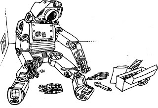
Robot Art of George Beker


Bot by George Beker

Probably one of the most influential books of my computer development was Basic Computer Games. This book that was developed in the 1970s by David Ahl was ahead of its time. 


I was a pre-teen with an APPLE ][+ computer (48k RAM),  no disk drive, no hard drive.  I would sit for hours and type the programs into the computer (it had a built in BASIC interpreter). Playing them was fun, and in the process, I was learning to code.

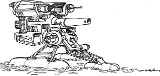
Perhaps more influential on me than the BASIC programs, was the artwork in the book.  This is the work of George Beker.

I found his "not of this technical reality" Robots to be inspiring for some unknown reason. They were everyday, melancholy looking, and sentient(!)  Loving them or not, It allowed me to visualize robots possessing a strong anthormothic spirit.

by George Beker

You can find more information about George Beker here.  The sites links are not all up to date. If you are interested in purchasing an ebook of his portfolio of robots you can find it at his publishers site: Kidware Software.  it also has the BASIC Programming book.

Also - if you found the BASIC Programming Games book to be inspiring, there is an Open project underway to modernize it with current languages. you can find more information about that here.


-G.Beker, you find my humble site, Thank You!

Saturday, December 18, 2021

Mojo4 - Additional Details (#4)

Here are some more details of Mojo4 - Quadruped Robot Dog

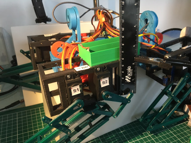
  NOTE:  This is a FRANKENSTEIN Prototype. ;)   it is built mostly with reused 3D printed parts. All of the Dark Green Leg parts were printed so that I could experiment with the 5-Bar design.  Everything else is reused or scrap from previous projects.  This includes the black frames used to mount the servo motors.  My plan is that once this is walking, I will start printing a new chassis with my new-found experiences, also to add the 12DoF.  But first this one must walk.


Here are the pictures:


mojo4-length-18dEC.JPG
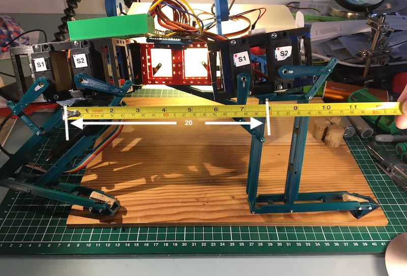
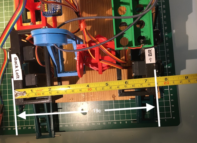
Length - measured from the pivot points:


mojo4-width-18dec.JPG
Mojo4 - Width measured on outside legs


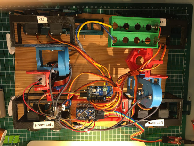
Top - Yes, this collection of PLA is a mess.  

Electronics:  Arduino Pro Mini clone, PCA9685 servo driver, and battery box. 


The 4 servo boxes are on the sides all held together by random parts that fit, bolted together by M3 screws and nuts, some super glue, and hot glue.  Somewhere in there is a 9V battery for the microcontroller, there is a small power switch on the mounting board.


mojo4-top-18Dec.jpeg


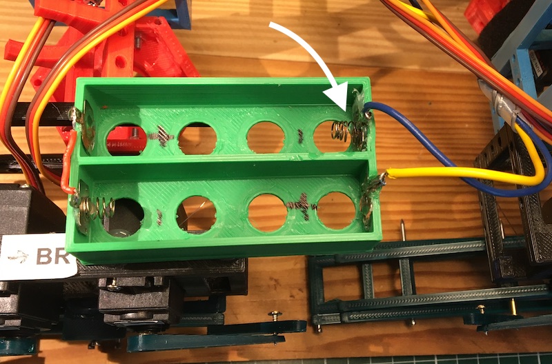
Battery Box:  3D printed, for 2x 18650 batteries. I reused the spring contacts from small toys.  This is a problem since the spring that I have highlighted with an arrow can not handle the current of the batteries and heats up (to the point of melting the hot glue holding it in place).  something else to fix. ;)


mojo4-battery-box.JPG
3D Printed Battery Box for 2x 18650 batteries


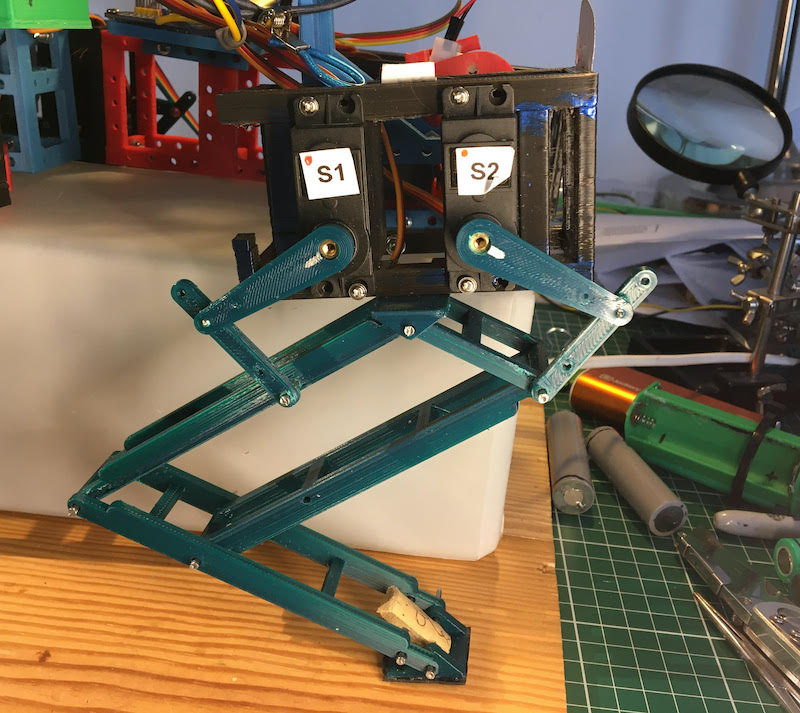
Here is a picture of the leg configuration.  3D printed, minimal material.  It has been strengthen (i made it thicker) to prevent bending. The pivot points are small common nails placed into tubular channels in the leg components. a very cheap easy way of making a hinge. The paw needs a new design.  the current version is 3D printed, has rubber on the bottom, and part of a wine cork to hold it in place.  reuse!  ;)


mojo4-leg-18Dec.jpeg
Mojo4 - 5bar quadruped robot leg


Thursday, December 2, 2021

Mojo4 - Half-a-Robot-Dog! (#2)

 Quick Update - Mojo4 is coming right along. I have a lot post about.  But, for now I will just share this quick video.

video: 1/2 of Mojo4


Over the last weeks, my focus has been on the Inverse Kinematics, I will post more about this shortly.  When I had success with the above Half-Dog, i ran into an issue with the Voltage and Current of the servos when used together.  I have just solve this issue and will also follow up with my learnings.

In the mean time, enjoy the video. And, fingers crossed, will have something more to show shortly.

Monday, September 6, 2021

Tilt! - A Self Balancing Robot (#9) - The Balancing Act


New Gearboxes are installed time to make the balancing happen. - with video!

Video


Ugh, I spent a whole session trying to figure out why the M6050 was not communicating with the I2C bus.  It was clearly visible but no connection.  It seems that the circuit would prefer to have 3.3V in the Vcc, I was sending 5V.  Switching to 3.3V solved the problem. On to the next stage.

here are the first results:

First Test default:

double Kp = 40; // First adjustment
double Kd = 1.1; // Second adjustment
double Ki = 0; // Third adjustment

This seemed to be working, but the reaction of the motors was a bit off.  Some quick searches of LMotorController motorController() didn't reveal too much.  But I do see a factor in the code for the left and right speed factor.  These were set to 0.6.  IF these are associated to tune down the PWM signal sent to the motors, then it could mean that it is under powering.  I moved these to .8 and got a much more robust effect on the motors. On to Tuning the PID

Second Set  Test  default:
double Kp = 50; // First adjustment
double Kd = 1.0; // Second adjustment
double Ki = 0; // Third adjustment

I am getting some oscillation now, the Kd starts to tune this down.  Clearly from the video the robot has a tendency to lean in one direction.  I adjust the frame by putting hot glue between the sections, just squeezing it in and letting it harden.  I also suspect that the battery (weight inside) may be shifting forward. Using some cork, have wedged it in to prevent momentive shifting.

Third Set  Test  default:

double Kp = 55; // First adjustment
double Kd = 1.0; // Second adjustment
double Ki = 0; // Third adjustment

This was the most aggressive on the Proportional control constant that I used in the First Session. Certainly a little more 'attack' on the balance change. Starting to get some stable oscillations. 

Forth Set  Test  default:

double Kp = 55; // First adjustment
double Kd = 1.0; // Second adjustment
double Ki = 10; // Third adjustment

With this change, I added the Ki - Integral constant in to the PID. The result of Integral is to help smooth out the oscillations. There is a negative effect of controller 'Wind-up' as the integral values do not dissipate quickly. However I do not think I experienced this in this session. 

Overall the new settings in this set were not as desirable as the previous settings. Stability, subjectively, was reduced. Also, it seemed that I had a 'short' or disconnect in the power - OR - the PID was overwhelmed and stopped for about 1/2 second. Tilt! just fell over, and then everything started back up. 

Weight Adjustment 

Finally, I added a moderately heavy weight to the top of the robot. I used a Transformer that I had salvaged out of speaker. The additional weight seemed to slow the 'jitter' of the oscillations. However, the motors were unable to overcome the falling weight when it was tilted.

It seems that the robot has a tilt that needs to be identified and removed.  This is also leading to instability.  perhaps it is associated with the 'level-ness' of the sensor.

And - after repeated testing the blue wheel started to fall off. This was a temporary solution to start with.  It seems the repeated jerking started to effect the friction connection that was holding it in place. 

Tilt! A Balancing Robot - 3D Printed, Recycled Motors

Next Steps

1) identify the source of the lean/tilt

2) attach some weight to the top

3) investigate using the 12V battery and 5V power source

4) investigate easy remote control solutions

Saturday, September 26, 2020

Milli (#9) - New Mount for Helix - and Crawling Video!

 Milli - a Bio/Math inspired crawling single actuator robot millipede - now with teeth!

Milli - Millipede robot - now with teeth

From the last post, you may have noticed that I had tried to print some "nodes" as a possible improvement to Milli the millipede. Well, that thought was not as successful as I had hoped. There turned out to be no flexibility and too much tension on the helix. With this in mind, I reopened the milli design and set to work on some design updates:

  • Offset the motor
  • add a gear reduction to the motor
  • add a bearing to main helix mount - to remove force on the motor itself
  • try out a new power source
  • Add teeth - because we need to add more Nightmare Fuel!!
CAD Design - new Motor Mount and Gear


The new design is a new motor mount, with drive gear, a bearing mounted main gear, and new 12V "shore" power.

3D printing gears remains a dark art to me, but here you can see that they are functional. In this print, I have used a larger Modul of 1.5, this makes larger teeth. I believe for my quick 3D prints this is a more accommodating solution (more tolerance for rough prints!).


I applied a liberal amount of hot glue to attach the pre-existing helix mount to the newly printed main gear. That may qualify this for a frankenstein prototype, no doubt.


Sloppy gears? certainly room for improvement - on the next iteration.  The thicker base layer print creates an uneven gear surface.

Another issue was the 'pede wheels' that I kept from the previous build. They function as wheels, however in the video you can see that the left wheel consistently unwinds and falls off, Doh!

Ready to Test!  Let's get crawling!


Milli - Robot Millipede on a colorful background


For this round of testing, I am using "shore power". The robot is tethered to a 12V DC source. I reused a momentary switch - also from a printer - in order to easily turn on and off the robot.

Testing goes as expected.  The motor gear hold, which is surprising.  However the front left pede-wheel falls off frequently.  The motion of the helix, continues to be smooth.  I believe the addition of the bearing smooth this rotation off, taking load off the motor.  

Video on YouTube:


Next Steps:


With this success, time to think of what would be in the next iteration.
  • Onboard 12V power supply
  • micro-controller with PWM output
  • Motor Driver board
  • remote or autonomous operation (Min1 project may come first)

Sunday, September 13, 2020

Current Thinking in the Robot Labs

These are things currently being thought about at the TENRA Robot Labs...

Late nights and early mornings in the lab!

3D Printing

Ah... the beauty of 3D printing for robots!   It is the magic of having an idea in your head, which leads to, a sketch on paper, a drawing in CAD, and then a solid print - or many prints:


1st - A quick sketch on paper

2nd - A quick draft in OpenSCAD

3rd - a quick print - a solid Object!

Finally - Repeat as needed

I really love this aspect of Rapid Prototyping. I find it one of the more enjoyable steps in robot building. At each step in the process, you can find opportunities or issues with your design. It is fantastically easy to go back a step or two and add improvement to the design.

A good example is in this very simple build of "Node", pictured above.  "The Node" is an experiment in the Milli Project. I wanted to explore the ability to move in two directions on the helix in order to improve the mobility of the millipede robot. 

At each step in the process, I found that new aspects of the build became evident.  Even in the first print, i realized that I need more of the 'feet' to touch the printer bed. A quick change to parameters in the CAD, and it solved the problem. Finally, a quick print of three copies of the nodes. I assembled them and was able to perform my tests. The result was that the solution would not work as is due to certain bindings. I was having a difficult time imagining this complex relation in my head.  The rapid development of the concept provides a fast path to success or failure, both are acceptable!


Min1 - what should it do at night? 

Min1 is the Minimal Viable Robot for the Totally Not Evil Robot Army.  But, I am just thinking, what can this robot do at night.  It is just sitting around, with nothing to do.  Idle cycles are the devil's playground, right? So perhaps it needs a few teeth and a sensor to seek things (like ankles) out and make stabby motions.  ;)

Min1 - outfitted with ultrasonic sensors and stabby teeth


Min1 ready to Roam - seek and stab


Min1 Robot - as a Franken-prototype ready to go

Tilt!

Tilt, the balancing - 2 wheel Robot, is sitting prominently in the TENRA Robot Labs. It is patiently waiting a more powerful power source.  Twelve Volts DC is not going to cut it, it needs more power to keep the recycled printer motors from stalling.  I have just recycled a 19V power adapter that I will use as 'shore power' for the next round of testing. 

I am really liking Tilts new 'eyes'!


Sunday, July 26, 2020

Tilt! - A Balancing Robot (#4) - Engineering the Wheel Mount


Perhaps this takes a little more thought than I first expected.  I am trying to build this robot using scrap parts from printers, standard components, and in this case the bearings and axels from a pair of inline skates. WELL... that lead to some issues with the wheel mount. Today, I am re-engineering this design and building the wheel mount.

First attempt to test the motor, belt and pulley

Here is are the parts. I was trying to rig them up to quickly test how much backlash I would get from the old printer motors and belts.  However, the axel and wheel were so wobbly that I could not make it work.  (In addition, my plans to use a piece of scrap pressed steel to attach the motor are dashed - I do not have the necessary tools to cut large holes in the steel.  so back to the 3D printer!!) Also, you will see, I am re-using the printer's belt drive. This is about 70cm in length.

Wheel, bearing, and axel from an in-line skate wheel

The design problem is how to use the already dimensioned Axel and Bearings. Since I am reusing this part, I must work around it's length. It is longer than what I will need. In addition to this concern, I will need a way to secure the axel to the base and wheel mount of the Tilt robot. This is not typically a problem with balancing robots that us stepper motors since they have more direct control of the wheel. However, I firmly believe that the weight of the robot should not be directly applied to the motor. Thus I am using bearing and separating the load from the motor.

Checking the alignment (modulus) of the belt and the 3D printed pulley

I sketched out the arrangement of the bearings and spacers and axel. It is necessary to 'plug' the bearing into both the wheel/pulley. While redesigning this aspect of the wheel, I took the time to inspect the belt to make sure the pulley's teeth aligned with the belt. This is based on the modulus I calculated. It seems to match.

On the frame side, i repeated the bearing housing, creating a mount that holds the bearing but provides freedom for the axis.  I am sure this will have another review in future robot designs. After printing, I will test out this new design.

Tilt - Wheel base design (in red) - OpenSCAD

For the frame, I am still unsure what materials I will use for the 30cm between the wheel axel and the motor. since I do not know, yet, I designed a simple 3D printed frame with 10mm separate holes for M3 bolts. With this design I will have the flexibility to use anything, and just bolt that to the structure.

Next Steps:

The next steps are to print out the new design and assemble a single wheel for testing. this structure will allow me to clamp the wheel to the table and test the tension on the motor. I will be looking at how much backlash or slipping the belt will have.

The next physical design step will be to find a way to connect the motor mount to the wheel mount.

Update:

Here is the printed wheel mount.  The scrap steel would not work very well. I currently lack the tools to shape it and bore holes through to attach to the motor mount. 

I did have two rods of medium length from printers I salvaged.  With the ability to print out parts, I printed a rod mount. The mount is adjustable using the rubber rollers that are already on the steel rods. (now i just need two more for the other side!)

A workable prototype for one side of the balancing robot

Saturday, July 11, 2020

Minions!

A Dream of Totally-Not-Evil-Robot-Army Minions!!


Minions - and not the D'zney ones!  Every Mad Scientist needs them.  Especially if you are going to build a robot army. Minions can be the foundation for any robot army, the very lowest of the 'foot soldiers'. What would be the robot equivalent?  Perhaps the most simplest robot configuration. In 'Agile' speak: the Minimal Viable Robot?

Robotic Minion with a Manipulator Arm

The Minimal Viable Robot, would have the minimal number of parts, and be the easiest to replicate. It could be small, one would say Miniature. A minimal, miniature robot - the first one in the Robot Army.  It will be a Min-i-on, and mini-one, a Mini1!

Lets build it!!  Because this Robot Army needs many many more robots!  It needs Mini1s!!

Mini1 sketches

Design


What is the bare-bones, minimalist robot, that still has some kick?  I would propose:

  • 2 Wheels
  • 2 Small Motors
  • a Motor Controller
  • Microcontroller
  • and a Battery

That sounds really basic. but, if it is going to do something - like to serve butter - in needs at least a sensor and a manipulator.

Here are some parts I have laying around the Totally Not Evil Robot Army Lab. This is a really cheap build with these parts. The Wheels are from an old printer. The motors came off of a chotsky fan I collected from a trade fair. The motor driver is a little overkill L298N but will do the job. The microcontroller is a Arduino Pro Mini (clone) about $5. and for power perhaps this battery bank battery 5V.  For a sensor, I have a common ultrasonic ranger HC-SR04.  And if I go for an arm, I will use simple micro-servos. In the bottom corner is a ESP32, which would be more powerful, and provide wifi/bluetooth - perhaps for future versions.

Potential Parts for a Mini1 - Robot Minion


Alright!  Let's get started:

Mini1 - first CAD sketch - OpenSCAD

Friday, July 10, 2020

Crappy Robot Stories #1: Secondhand Love

 Crappy Robot Stories...


The front door to the shop slammed open andValk stalked through, block trench coat swirling around his ankles. He marched through the store, past the ranks of metallic soldiers standing motionless, to the counter at the back of the store. Beneath the display cabinet, rows of motherboards and semi-organic AI’s sparkled in the lights.
              Val slammed both hands down on the glass.
              “I demand a refund!” he shouted at the clerk behind the counter. Electricity sparked off of the stray white hairs that stood out in all directions from his head like a puffy cloud.
              The clerk behind the counter didn’t flinch from the sudden noise. Instead, he slowly dog-eared the page of Evil Today that he was reading before closing the magazine and laying it off to the side. Finally, he raised his bored gaze to the puffing scientist on the other side of the counter.
              “Welcome to Secondhand Evil, how can I help you today?” he intoned.
              “I demand a refund for… for… for that!” Valk shouted again, pointing behind him. As the clerk looked, a metallic head with a single eye widget poked around the villain’s back.
              “Hello,” the robot whirred. “My name is Bobs, minion robot 001.”
              “What seems to be the problem?” The clerk asked.
              “It’s supposed to be an evil robot. I specifically asked for the Villainy 2.0 software to be installed, and it hasn’t been!”
              “All our models come standard with the henchman software Villainy 2.0 installed. Why do you believe your model does not?”
              “It doesn’t do anything evil!”
              The clerk sighed and pulled a complaint form out from beneath the counter. “Can you give me some examples?” he droned.
              “I told it to prepare the lab for experiments, and it cleaned my lair. The floors are freaking sparkling!”
              The clerk looked up, one eyebrow raised.
              “I had just the right amount of evil chaos! It’s too neat now! It interferes with my evil creativity!” Valk screeched.
              Behind him, gears whirred as the cycloptic robot peeked around its owner again. “There were roaches.”
              That’s not the point!”
              “Okay, it cleaned without command. Anything else?” The clerk asked.
              “Yes! I identified a homeless man that would make the perfect minion, and I sent Bobs out to recruit him. The guy was recruited…. to an IT firm as a manager! He now makes six figures and can comfortably support his family!”
              The clerk rolled his eyes and began to scrawl on the form. “Failure to follow directive to necessary level. Anything else?”
              “He made me contribute to the middle class. I loathe the middle class!”
              “Yes, yes, I know the Evil Rulebook as well. Anything else?”
              “He’s constantly baking cupcakes. My entire lair smells like vanilla!” Valk’c chest heaved as he turned to glare at the robot.
              The clerk looked at the robot as well. Bobs held up a pink box and offered it to the clerk. He opened it up to a perfectly frosted cupcake, wrapped in a lacy doily.
              “Oookay, that’s a new one,” he said slowly. “Are they any good?”
              They’re delicious!” Valk screeched. “And they aren’t even poisoned? What kind of villainy is that?”
              “I see.” The clerk closed the box and stored it beneath the counter. He pointed up above his head, at the large sign suspended from the ceiling.
              All purchases are final. NO REFUNDS, NO EXCHANGES.
              “Oh, come on, you have to do something for me!” Valk insisted. “What about in-store credit?”
              “Nope. All sales are final. You acknowledged the risks of buying a second-hand robot when you signed the contract with us. Would you like to see your signature? I can pull up the agreement right now.”
              “I want to see your manager!”
              The clerk rolled his eyes. “I mean, I can call her if you want me too, but she said she was working on her death ray and she was going to use anyone who interrupter her as target practice.”
              Valk glared at the clerk, who stared back with the dead gaze of someone who had spent way to long in retail.
              “Fine!” he snapped, spinning around. “Bobs, we’re leaving. Se if I ever come to this stupid store again! I’m going to tell everyone how terrible the place is!”
              The robot waved one, then raced off after its master with a whirr of gears.
              The clerk sighed, shook his head, and flicked his magazine open.
              “Cupcakes,” he sighed. “Really?”