Sunday, July 22, 2018

Mojo (#11) - First Walk - A Compliant Quadruped Robot

Mojo is walking!  ... somewhat  :)


All of the pieces are in place, and now the walking trials, tuning, and real work begins.  In the video, you can see the current iteration of robot and code. I removed the heavy tether and replaced the power sources. With the lighter power tether, it is just about walking. Sure there are some slips and a lot of falls. But, in this video you can see it make a few strides and move itself under its own motion!

Mojo Current Config, with power supply
This is the current configuration of Mojo - The Compliant Quadruped.

  • Robot Chassis is 3D Printed: Servo and Control Frame, 4x Legs - with 4 linkages and a self made Serial Elastic Actuator, thread, springs and metal rods and screws from a salvaged printer.
  • 8x 9g SG90 type micro Servos
  • PCA9685 16-channel servo control board
  • Arduino Mega 2650 micro controller
  • Power: 9v transistor for Arduino board, 5v 2amp Power bank for servos
  • Other Salvage: power switch, 9v transistor connector, barrel jack, USB cable, pieces of rubber from bicycle tub, etc.  :)
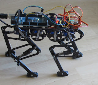
Quadurped ready to walk!

Mojo back top view
Lessons from the walking trials:  

There was a lot of "weakness" from the Left Hind servo.  It felt hot to the touch - so pretty my burnt out that motor.  This was the second failed servo. These are cheap servos, so I am expecting to go through them. (need to place another order).

The back legs have slippage and do not seem to be getting a full swing. I did identify some bad parameter setting in my code, and that seemed to help.  I also increased the pull on the knees.  for the swing phase, I will increase the distance from 50 degrees to 80 degrees. I am hoping this provides more momentum forward and lefts the back up more. 

Need sticky feet to help with the sliding.  maybe even change up the size of the front/hind legs.  But, the next big changes coming will be in the chassis frame.  it will be much bigger, have rollbars, a second deck to raise the knee servos, and have space for a control panel for switches, an interupt, and status led.  It was printing while this version was walking (you could hear it in the back ground!)
Next version of the robot frame (CR-10 3D Printer)


Monday, July 16, 2018

Mojo (#10) - Design Changes - A Compliant Quadruped Robot

Mojo's legs are moving with the first Gait program, but only flopping around on the surface. A number of issues are preventing forward motion.  The biggest are:
1) the Trot Gait may be too ambitious.
2) the 'fibia' is too lax.
3) the tether is too stiff and heavy

To address these issues:

New Gate:  Slow Lateral Sequence Walk (75% Duty Factor)
I recoded the micro-controller to serve up a better sequence for moving the servos.  This new motion is called a Lateral Sequence moving LH-RF, then RH-LF in a slow gait. The new sequence is has a 'duty factor' of 75%, meaning that the feet are on the ground 75% of the time. This is also officially designated as a "Walk". While the feet are on the ground, they are constantly moving backward to propel the robot forward.  For 1/3 of the gait, two of the legs will be off the ground.  The sequence looks like this:

Start 1 2 3 4 5 6 end
25 25 35 45 55 65 45 25
125 125 115 135 155 145 135 125
65 65 45 25 35 45 55 65
155 145 135 125 115 135 155 155


The columns represent the 'segments' (my term) of the gait. there are 6 segments in 1 complete cycle.  The values are the 'starting angle' in that segment.  Green represents ground contact, Red represents leg lifts. From this I created a matrix that provides the rate of angle change per segment. The leg lift is 4 times faster than the ground contact.

I am quite happy with the code, it refactored down quiet nicely!

  //cycle: segments 6 X 10 steps X 8 servos
  for(int seg=0; seg<=5; seg++){
    for(int qStep=0; qStep<=stepCount; qStep++){
      for(int x=0; x<=7; x++){
        angle[x]=angle[x]+seq[x][seg];
        pwm.setPWM(x, 0, anglePulse(angle[x]));
      } 
      delay(stepDelay);     
    }

  }

Fibia
The Fibia linkage of the leg is much to lax, and allows the robot to 'stumble' over its own feet. The picture below shows the problem area. you can see that the bottom leg segment is often too far back and should be in the 'green' position.
tibia section of the robot

The quick fix for this is to replace my spring linkage with a solid linkage. A solid piece would complete the 'Pantograph' more completely.  luckily, the tibia on the bottom of the linkage would also suite for the fibia.  So a quick print should solve this problem.
Tibia now Fibia
Tether
This I still need to work on.  I need A) Power for the servos at 5V and B) Power for the Arduino with a barrel connection. Then I will have a stand alone solution, but I still need to connect to the laptop to update the code.  

The current tether is heavy compared to the robot and is impacting its ability to move!

Sunday, July 15, 2018

Mojo (#9) - Walking on Air - A Compliant Quadruped Robot

Mojo is walking on air! 

I started writing the code to get all of the servos moving. After some initial "lean" and "kneel" movement, I created the first walk sequence.


Simple walk, is anything but simple - this is going to be where the challenge really starts. To best understand this, read the wikipedia article on "Gait".  There are many factors to consider in creating a stable gait. So I knew the first one will be the hardest. It will be a few iterations before I can get something stable.

For my first motion test, I am going with a basic trot. In this case, I am moving the Right Front (RF), and Left Hind (LH) simultaneously.  So RF-LH are pared, a LF-RH are paired. A single stride is divided into four quadrants where the leg rises half the time and moves backward half the time. On the rise, the knee joint is quickly raised and released.

The video above show the motion in the air.  The video NOT shown, shows mojo falling down like a drunk! :)  at least not yet...

Top View of Mojo


Tuesday, July 10, 2018

Mojo - A Compliant Quadruped Robot (#8) - Raise Your Front Right Leg!

Mojo is ready to start moving!

I finished printing the newly designed SEA actuators.  Replaced the old ones with the new and wired up the Cam Cable to the front right leg and gave it a whirl.  It can twitch now!!


This movement is combination of raising the leg (femur) servo by about 28 degrees and pulling the knee in by about 115 degrees.  

In the video you can see the cam, the disk attached to a servo pull a cable (thread) back. This motion pulls the foot (tarsal) up by bending at the knee.  You can see the SEA spring compress.  Meanwhile, the leg is raising slightly, the combined motion lifts the foot off of the ground surface.  The other legs are in "Stand" position.  All of the servos are energized, so the legs have 'stiffness' to help it stand up.

of course lots of learnings:

  • leg can collide with the cam
  • the cam cable regularly comes off the cam
  • thread for the cam cable will not be durable enough
  • lots of Arduino code to manage


its a small step...  but just the beginning!


Mojo - 9 July 2018
Hey all my coding buddies!!
here is the code for lifting the leg.  It needs refactoring.  What is a better way for me to do this?  please make a suggestion and get back to me!  You know where to find me!

[code]
void leg_lift(int leg, int knee) {
  Serial.println("Leg Lift");
  int stepCount = 28;
  int kneeStartAngle = 25;
  int kneeEndAngle = 140;
  int legStartAngle = 158;
  int legEndAngle = 130;
  int kneeStep = int((kneeEndAngle - kneeStartAngle) / stepCount);
  int legStep = int((legEndAngle - legStartAngle) / stepCount);
  int kneeAngle = kneeStartAngle;
  int legAngle = legStartAngle;
  for (int x = 0; x <= stepCount; x++) {
    pwm.setPWM(knee, 0, anglePulse(kneeAngle));
    pwm.setPWM(leg, 0, anglePulse(legAngle));
    kneeAngle = kneeAngle + kneeStep;
    legAngle = legAngle + legStep;
    Serial.println(legAngle);
    delay(25);
  }
}
[/code]

Sunday, July 8, 2018

Mojo - A Compliant Quadruped Robot (#7) - SEA v5

Hi all, back to work on the walking robot after a short break!

Third time is a charm!  I left on break knowing that the servos on Mojo-bot were not going to be strong enough to pull the knee joint in.  That would leave me with only a few easy options.  
  • Use stronger servos - the 9g micro servos are cheap, but really limited on torque. My preference is to stay with the cheap servos for now.  The next grade up is a substantial cost increase.  The current set I have now are around 2 bucks a piece.
  • Mini-Mojo - revamp the whole design to be much smaller.  This option would yield a smaller bot, that is perhaps in the strength range of the servos.
  • Re-Design the Serial Elastic Actuators (SEA), Again!  - this will be the 5th Design version. But, if I went with Mini-Mojo a new design would be required again.
The SEA is by far the most complex component of the robot. I am envious of EPFL because it looks like their SEA is easy.  But, some internet searching turned up no commercial version. Since I am using re-purposed printer parts for my robot, I decided this might be the best option.  I have 4 lighter weight springs that would work better for the servos. And, I could improve the transitional forces on the SEA by imbedding a metal rod from the printers into the core of the linkage.

Off to the Drawing board!

I decided to revisit the design with a piston/plug that is inside of a forked chamber. Because I am using OpenSCAD with variables, I could keep my existing design doc, and just make modifications. Instead of using a "Fork" from my very first version, I would create a cylinder that could be glued to the connector.  This would require I put a "plug" at the end of the piston - also gluing together.  The rod would be embedded into one connector, allowed to freely ride inside the other connector.  This would provide good translational support. I just need to be careful with the friction of the plug inside the cylinder.

SEA v5 - First Attempt

The first designs looked like the above.  It took three iterations of printing/assembling to dial down all of the parameters. I needed to increase the cylinder wall size, that broke just extracting from the print bed. Adjusting the diameters, changing distances, adding additional expansion slots, and counter sinking the plug, etc.

Parts for the SEA v5

The 3rd variation on the 5th design, started to actually work. The tolerances were tight enough that it did not require any glue.  but I will add a drop before I start kinematic tests.

New SEA v5 on top, vs SEA v3
The new design is much easier to compress.  It has almost negligible translational (side to side) movement, which is very important in this application. The resistance due to friction seems to be manageable (we will see in testing).  Also, the new design has more range, going from 8mm of compression travel to 10.7mm.  This will work better to bend the knee.

I will have to comment, that the old design had a better 'esthetic'.  :)  the big spring looks impressive - but proved too much for the little servos!  Now to print the other three out, put them on the robot and get it twerking again! :)