Saturday, September 29, 2018

Mojo2 (#15) - Leg CAD Design and Actual Testing

Mojo 2 is a compliant quadruped walking robot dog - in the making.

Currently, I am testing and making improvements to the design of the Leg Modules. The video below shows the progress of the second iteration of the leg design. The biggest improvement was a re-worked Cam which pulls the leg up bending at the knee and compressing the spring (this completes a Serial Elastic Actuator of sorts)


The new cam is larger than the previous version. the increased size will create more pull on the leg with the same amount of angular change.  Thus it will pull the cable farther and faster.

I was also able to correct a design oversight regarding the positioning of the Cam relative to the guide post on the leg.  by adding a mounting spacer, the cam is in the correct position. One of the best parts of using a CAD is that by manipulating all of the parts in the CAD system, it is possible to identify the issues and (hopefully) resolve them in design stages - prior to printing.


Mojo2 - OpenSCAD model
OpenSCAD can be a challenge to learn at first, but if you think like a programmer, it makes CAD designs very precise, and easy to manipulate.


OpenSCAD Leg Model and Actual


Sunday, September 23, 2018

Mojo2 (#14) - New Design

If you are following along the design posts for Mojo - The Compliant Quadruped Walking Robot Dog - you have seen the development go through multiple iterations, the result of testing and trails.  Some trails have been very positive, such as better SEA design, others out right failures, such as the 'knobby knee' version.

Currently, the design calls for stronger servo motors to 'complete the step' in the walking gait. New servos call for stronger springs, which call for bigger SEA. This will also solve the issue of the weight of the robot consuming too much compression of the springs. The larger servos will also require a new Chassis/frame design.

the new chassis will be modular, which will allow for the width and length to be adjustable. Each 'leg component' will be a separate module that is bolted together with the other components. To make the robot wider a 'spacer' can be added between the components.

New Modular Leg Component Frame
SEA blue
The new Mojo will support larger springs. A new Serial Elastic Actuator (SEA) was created for the new larger springs. The SEA v5 version was reused, just scaled for the larger springs. In the picture, you can see the evolution from the "knobby knee" leg with the small SEA, to the new SEAs and Part of the new leg.


New SEA in Blue
Cable and Cam
on of the most frustrating parts of the original mojo build was the Cable & Cam system used to lift and pull the knee up. The first design used regular thread as the cable. The thread was connect to a 3D printed Cam on a servo. The thread ran over a printed 'post' on the hip, which was a decent design decision. Finally it was 'tied off' on a screw/or bolt connection at the base of the SEA (on the tarsal part of the leg). This build had constant problems with the thread coming off the Cam, and was difficult to have a fast connection on the leg.


Evolution of th Cam
The new design will use Fishing Line as the cable.  Fishing line is durable, smooth, and strong. The path will be the same, but will use "eye bolts" at the hip and leg. The option of a straw tube may be considered if the cable continues to come off of the connectors. teh ETH Zurich robot used a 'tensioner' system at the hip that has not been considered due to complexity at this time.
Mojo2 Leg Configured and ready for testing
Paws, feet, and other distal configurations
Mojo will need new feet. The new design will attempt to add some compliancy by using a expansion spring at the heel. Having a rubber sole for the foot will help in the gait. too soon for claws? :)

Film at 11...

Wednesday, September 19, 2018

Bug (#2) Building a Walking Quadruped - Now in Video!

The "Bug" is now walking!

here is the video on the Totally Not Evil Robot Army Youtube Channel:


The video tells the story of building the robot bug.  you can also find details in the my original post here.

For those interested in the gait, I have created a "Quadruped Crawl" for 2 DoF (Degree of Freedom - servo joints) legged Quadrupeds.
The gait is designed to keep the center of gravity of the robot inside the three legs that are static to the ground.  The key to keeping this balance is to 'tilt' the robot back on the opposite leg that is not moving.  This will create a 'wobble' in the gait, but otherwise provides better success at moving the leg.

If you are interested in learning more about gaits for static quadrupeds with 3 DoF there is a good write up found here on Make Magazine.

Saturday, September 15, 2018

Bug: Rapid Prototyping the Bug (#1)

In my imagination, there is an epic battle in my Garden between "The Gardener" Robot and Slugs that eat my Marigolds! "The Gardener" will be one of the many members of my Totally Not Evil Robot Army.  Now, I just need to render the gap between imagination and realization.


The Gardener vs. Slugs!
To get there, "The Gardener" will need a good set of Quadruped legs!  Getting a Dynamic gait with a Compliant Quadruped can be tricky. I wanted to have some form of quick success in getting "Mojo" to walk. Perhaps it would be best to quickly build a 'Static' Quadruped and learn to make that to walk first.  This would provide an opportunity to work on the software for the gait sequence and understand a little more about getting a quadruped to walk - albeit slowly. And it will be really cool!

I decided to build a Quadruped with only 2 servos (2 degrees of freedom) per leg. These types of robots look anthropomorphically more like Spiders or Bugs rather than Dogs or Cats.  So, I will use a working name of "Bug" for this beast!


From imagination to Sketch - the pantograph leg
Once I have an idea in my imagination about what it will look like, I like to create a basic sketch on paper of what the main mechanism will look like.  Then I with some basics in mind, move the sketch/idea into OpenSCAD to design the 3D parts.


OpenSCAD image of the Bug Leg with two pivots
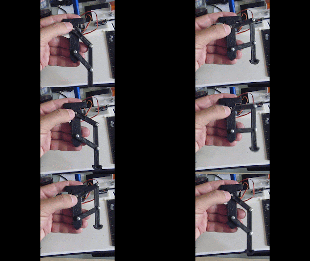
In this design a simple 'pantograph' linkage will be used to move the leg up and down. a single servo can perform this action. one benefit of the pantograph design is that not all of the weight of the robot will be put on the servo. I feel this will be very important for all servo designs.


pantograph leg for the Quadruped

The design is moved from OpenSCADA to Slic3r to gcode and the 3D printer.  Parts are printed and tested.  I cycle through a few design iterations this way, to fine tune locations of the servo braces, clearances, and sizing. It is very easy to overlook placements, and having incorrect tolerances.


Physical prints next to sketched ideas
Here the legs are connected with servos and the microcontroller

The design is checked along the way to make sure each part fits correctly. Having the physical piece is extremely important to the design process. It is hard to realize the small corrections needed from just a CAD program.  For instance, the ball pivot of this construct  was too small in the 3D printing process to handle the forces of the screw that was used, forcing it causes it to split. This leads to modifications in the design before I print the next set of legs.


Printed leg connected to controller and battery

Early tests with the servos, driver, and microcontroller, are essential for validating the mechanism.  it is also useful for starting the code base that will be used to control the legs.  Once satisfied that 1 leg will work properly, I printed the remaining 3 legs of the Quadruped.


OpenSCAD drawing of the complete Bug - version 1
Using OpenSCAD it is easy to create a drawing with each of the pieces in the correct locations. With this approach, it is possible to draw out what the finished robot will look like.


Bug Quadruped almost assembled
Here on a messy workbench is the almost (3 of 4 legs) assembled prototype.  Fitting all the pieces together and making room onboard for the battery, microcontroller, and servo driver board.  

From idea to prototype quickly!  Most of the design was done on a Sunday morning, while printing was done every few hours during the week.

The next task will be to create a stable walking gait, this is surprisingly non-trivial.  I will share that in a future post.  Time to get this beasty walking!!

Wednesday, September 5, 2018

Sailing Robots of the World

Congratulations to the "SB Met" Autonomous boat for the successful crossing of the Atlantic Ocean.  This is the first "unmanned" sailing robot to win the MicroTransat by crossing the Atlantic Ocean.


SB Met - Ocean Sensing AS Robotic Boat

Here is a nice article about the successful completion written by the San Francisco Chronicle:  Robot boat sails into history by finishing Atlantic crossing

The concept of autonomous boats sailing the Earths Oceans has been developing rapidly over the last few years.  A convergence of robotic technology, remote communications, and better batteries/solar have created an opportunity for new robots that can sail autonomously. These vessels are much more capable than drift buoys, having either sails, motors, or 'wave gliders' to provide propulsion. Adding the in the lowering cost of satellite communications, it is possible to create lower cost sensor platforms that can travel long distances on open water.

There are a few Robotics Challenges that have been created to spur innovation and attempts to make record setting crossings.  The Micro Transat has been running races for teams to compete annually by either Autonomous or "Unmanned" robots crossing the atlantic.  Only this past year have serious competitors been able to complete the journey. "Serious" meaning craft that are built to withstand the beating ocean waves, minimal sunlight, strong currents, and harsh salt water. This year Ocean Sensing AS entered it's "Sailbuoy", a sensor platform built to autonomously withstand the North sea and collect data for days before returning to port.

Robot Challenges:
MicroTransathttps://www.microtransat.org/
World Robotic Sailing Championships - http://www.roboticsailing.org/
The Sailbot competition - http://www.sailbot.org/

There are a few various projects and companies that have been started in the last few years.  Most interesting are the Individuals and groups of Makers that are building Autonomous robot boats.
SeaCharger by Damon McMillian

Damon McMillan had great success when his "SeaCharger" navigated from California to Hawaii, and then from Hawaii to (nearly) New Zealand.

Project Ladon
Project Ladon is also building an Autonomous Boat with intentions of being the first to sail Around the World

The ambitious BlueBird Project is building the SeaVax robot to scoop-up ocean polluting plastics.

There are a few companies that have been created to build Autonomous boats
Sail Drone, Alameda, California:  https://www.saildrone.com/
Ocean Sensing, Bergen, Norway:  http://www.sailbuoy.no/
Liquid Roboticshttps://www.liquid-robotics.com/  - makers of the Wave Glider
Teledyne Marine: http://www.teledynemarine.com/slocum-glider - makers of Slocum Gliders

More local applications for environmental monitoring include project and companies like:
Robot-fish made for Project Shoal
Vertex AUV by Hydromea, an Autonomous Underwater Vehicle

There are many more, if you have a favorite system that I did not mention, please post it in the comments section.

It is a wonderful time we live in! It is time to create robots to explore our world and beyond!