Showing posts with label Motors. Show all posts

Sunday, June 23, 2024

Mojo5 - Enhancing Performance with More Powerful Batteries (11)


Mojo5 - with power bank battery

Welcome back to the "Totally Not Evil Robot Army" blog. In this 11th installment of the Mojo5 series, we’re going to dive into a crucial aspect of building robust quadruped robots: using more powerful batteries to drive hobby servos. Specifically, we'll explore how increasing the available amperage and voltage can significantly improve the performance of underpowered servos and the considerations needed to ensure safe and efficient operation.

The Problem with Underpowered Servos

Building a quadruped robot like Mojo5 with cheap hobby servos often leads to performance issues. Many of these servos, such as the MG995, are slow and lack the torque needed for dynamic movements. Even with a 5V power supply, these servos can become wobbly and unreliable, especially under load. This is where upgrading to more powerful batteries comes into play.

The Limitations of the Original Power Configuration

Initially, Mojo5 used a 5V 12000mAh power bank. While this power source had a high capacity, it was limited to a maximum output of 3A. Given that the MG995 servos have a stall current rating of up to 3A each, the total current demand for the robot could easily exceed 20A during peak operation. This significant shortfall in available current was a primary cause of the robot's poor performance.

Upgrading the Power Source: LiPo Batteries

Based on previous discussions and experiments, we found that using a more powerful battery can drastically improve servo performance. Upgrading to a LiPo battery with a 2200mAh capacity, 7.4V voltage, and a 50C discharge rating provides the needed boost. This battery can supply well over the 20A needed by the servos, addressing the current limitations of the previous power source.

Considerations for Over-Volting

  1. Risk of Burnout: Exceeding the servo’s voltage rating does carry a risk of burnout. However, anecdotal evidence suggests that slight over-volting is generally safe if monitored properly. Implementing a voltage regulator could limit the current capacity, which might be counterproductive. In general voltage regulators on servo power sources are not recommended.

  2. Separate Circuits for Different Servos: For servos with lower voltage ratings, such as the MG90 (max 6V), consider creating a separate circuit to avoid over-volting. This will add an additional circuit which can be problematic. For my experiments with Mojo5, I used the same circuit.

Practical Application: Experimenting

Initial Setup

  1. Battery Connection: Connect the 7.4V 50C LiPo battery directly to the power bus of the PCA9685 servo driver, bypassing capacitors and regulators. This setup ensures the servos receive power directly.

  2. Handling Large Wires: Safely connecting XT-60 battery connectors and their thick 12 AWG wires to smaller electronics is challenging. Using a bare copper PCB or prototyping PCBs with multiple copper lines can provide a more robust connection. Soldering all wires together is an ugly but space-efficient solution.


Not Recommended!


In this experiment, I took the short cut and soldered the large wires directly in to a dupont connector. The connector was connected directly to the servo bus. This is not a recommended practice! I better connection with larger wires is recommended. In this particular case, as long as all of the servo motors do not stall, then only brief seconds of +20A current would be expected.  Current greater than 7A for sustained periods of time would destroy the connectors.

Experiment Results

After connecting the 7.4V battery:

  • Servo Performance: There was a noticeable improvement in servo actuation. The MG995 servos operated better, with no immediate burnout.
  • Heat Management: Monitoring the temperature of connectors and wires is crucial. Using a finger-test method (keeping fingers on components for one minute) can help identify safe current levels. If components become too hot to touch, reduce the current.

To visualize the improvement, I have embedded a short video showing Mojo5's performance with the original 5V power bank versus the upgraded 7.4V LiPo battery. Notice the difference in servo response time and stability.


Long-Term Solutions

While the initial experiments are promising, long-term solutions require more robust hardware:

  1. Custom Servo Driver Board: Developing a servo driver board with better connectors and thicker traces can handle higher currents more efficiently. This would replace the PCA9685 board, which is not designed for high current loads.
  2. Current Monitoring: Implementing current measurements and safety features like e-fuses can prevent overcurrent situations and protect your components.

Conclusion

Upgrading to more powerful batteries can significantly enhance the performance of underpowered servos in your DIY robots. While there are risks associated with over-volting, careful monitoring and proper hardware can mitigate these risks. As we continue to push the boundaries of DIY robotics, sharing these experiences and solutions will help us all build more capable and reliable robots.

Saturday, September 17, 2022

Robot Runner (#2) - skinny leg gets thicker

The skinny protype leg needs to be wider to support the robot. In general in needs to be more robust and handle the sideways transitional forces. To do this I am making the leg as wide as the 'pin' in my previously designed hinges. This pin is a 40mm finishing nail, which I have a box of. I have used them has hinge pins in the design of the wild weasel and Mojo4.  This will provide some of the support needed for the sideways forces. The design must be carried forward down to the lower leg and foot.

Robot Running Leg Mechanism -v2

As the width of the robot increases, it is not possible to determine on which side the compliant link will go and the placement of the crank and crank gear. The back lifting linkage, does not need to be 'wide' as it is only projecting the motion, not the support.

Robot Running Leg Mechanism CAD (pins not shown)

Also in this step, I am starting to think of how to drive the crank gear with a motor.  I have a 3D printed gear box from a previous design to reuse (Tilt! and 3D gearbox).  This gearbox will allow the robot to be driven by a brushed motor from a recycled printer.

Here is a video of the current design step:


As you can see, there is a lot of movement generated by the motor. The leg is thrown around creating an oscillation and some unwanted impulse movement.  This will need to be considered (dampened)in future design steps.

Monday, September 6, 2021

Tilt! - A Self Balancing Robot (#9) - The Balancing Act


New Gearboxes are installed time to make the balancing happen. - with video!

Video


Ugh, I spent a whole session trying to figure out why the M6050 was not communicating with the I2C bus.  It was clearly visible but no connection.  It seems that the circuit would prefer to have 3.3V in the Vcc, I was sending 5V.  Switching to 3.3V solved the problem. On to the next stage.

here are the first results:

First Test default:

double Kp = 40; // First adjustment
double Kd = 1.1; // Second adjustment
double Ki = 0; // Third adjustment

This seemed to be working, but the reaction of the motors was a bit off.  Some quick searches of LMotorController motorController() didn't reveal too much.  But I do see a factor in the code for the left and right speed factor.  These were set to 0.6.  IF these are associated to tune down the PWM signal sent to the motors, then it could mean that it is under powering.  I moved these to .8 and got a much more robust effect on the motors. On to Tuning the PID

Second Set  Test  default:
double Kp = 50; // First adjustment
double Kd = 1.0; // Second adjustment
double Ki = 0; // Third adjustment

I am getting some oscillation now, the Kd starts to tune this down.  Clearly from the video the robot has a tendency to lean in one direction.  I adjust the frame by putting hot glue between the sections, just squeezing it in and letting it harden.  I also suspect that the battery (weight inside) may be shifting forward. Using some cork, have wedged it in to prevent momentive shifting.

Third Set  Test  default:

double Kp = 55; // First adjustment
double Kd = 1.0; // Second adjustment
double Ki = 0; // Third adjustment

This was the most aggressive on the Proportional control constant that I used in the First Session. Certainly a little more 'attack' on the balance change. Starting to get some stable oscillations. 

Forth Set  Test  default:

double Kp = 55; // First adjustment
double Kd = 1.0; // Second adjustment
double Ki = 10; // Third adjustment

With this change, I added the Ki - Integral constant in to the PID. The result of Integral is to help smooth out the oscillations. There is a negative effect of controller 'Wind-up' as the integral values do not dissipate quickly. However I do not think I experienced this in this session. 

Overall the new settings in this set were not as desirable as the previous settings. Stability, subjectively, was reduced. Also, it seemed that I had a 'short' or disconnect in the power - OR - the PID was overwhelmed and stopped for about 1/2 second. Tilt! just fell over, and then everything started back up. 

Weight Adjustment 

Finally, I added a moderately heavy weight to the top of the robot. I used a Transformer that I had salvaged out of speaker. The additional weight seemed to slow the 'jitter' of the oscillations. However, the motors were unable to overcome the falling weight when it was tilted.

It seems that the robot has a tilt that needs to be identified and removed.  This is also leading to instability.  perhaps it is associated with the 'level-ness' of the sensor.

And - after repeated testing the blue wheel started to fall off. This was a temporary solution to start with.  It seems the repeated jerking started to effect the friction connection that was holding it in place. 

Tilt! A Balancing Robot - 3D Printed, Recycled Motors

Next Steps

1) identify the source of the lean/tilt

2) attach some weight to the top

3) investigate using the 12V battery and 5V power source

4) investigate easy remote control solutions

Friday, August 13, 2021

Gearboxes for Recycled Printer Motors (video)

 For those interested in making Gearboxes for Recycled Printer motors.  I have posted a video on my YouTube Channel that shows the asseymbly of the gearbox. Unfortunatly, it is not an instructional video, but it does show how to build it.


Monday, August 9, 2021

Tilt! - A Self Balancing Robot (#8) - New Gearbox for Motor and Wheels


A new gearbox for the self balancing robot.

The reuse of the pulley system is not working on the robot. Therefore, I started the whole gearbox design for recycled printer motors.  Now that there is a somewhat functional gearbox, it is time to return to Tilt! and see how the gearbox can be applied.

Here are the parts!  Now, just Engineer a new Motor mount and Wheel assembly!  


Engineer That!

New Motor Gearboxes layout with the old mounting brackets

Rough draft started - the concept of the new mounting system will be similar to the previous design iteration. Now, instead of using pulleys on a wheel with an axel, the axel will be directly part of the output shaft of the gearbox.  There will be a single 22mm bearing to take the load/weight of the robot instead of transmitting that to the gearbox/motor.

New Motor mount and gearbox

The New motor mount is wider than the original chassis and will fit 'around' the existing battery box. This frame will take use of the 1cm holes to allow for easy modular construction.  The gearbox, has new brackets so that it can be screwed to the new mount.  The old wheels are reusable, I will have a friction dependent plug that sets in the hub of the wheel and securely fits the output shaft of the gearbox.

Tilt with new 3D printed Gearbox - more Torque, less speed

NEXT:  Look for the new video showing the assembly of the gearbox. This is not a full instructional video, but does show how a simple gearbox can be 3D printed to allow for the use of recycled printer motors in robot construction.

Sunday, July 11, 2021

Gearboxes for Recycled Printer Motors (#2)

The final prototype build of the 3D printed gearbox for using recycled printer motors.  To see the initial development, see Part 1.


Gears
First version of Gear Design (above) vs. Current version (below)

Here are the versions changes from my initial gear design to the current one used.  The latest version has fewer teeth and is slightly wider on the smaller in-set gear.  This has required the housing box to be increased in size.  I used this extra design cycle to increase the distance between the axles in addition.

First version (right) vs. Current version (left) - output gear/shaft missing from picture


The Assembled Gearbox
unfortunately, you can not see the internal gears, because of the inclosing housing.  This design is working.  It seems to be good tork on the output shaft. The rotational speed is significantly less (~6:1) than the motor speed.  Even better, it will run without getting jammed. 

The next steps will be to design in a method for securing the gearbox to the robot. This may be dependent on the robot it is being applied to. The gearbox increases the space required for the motors.  My robots tend to be small, so this will have significant impact.

In addition, I would like to remove the load from the output shaft using 8mm skateboard bearings.  Finally, the drive shaft will need to be adjusted to provide a better attachment method for the output. 

Recycled Printer Motor 3D Printed Gearbox - First Complete Prototype Build


Robot Application
Since 3D printed gearboxes are not the focus of my robot building, this initial disign is good enough for now to move forward.

The Milli Robot will be fitted with the new gearbox. The connection between the motor and the helix shaft has been problematic. The rotational rate was too fast. Frequent jamming (due to a broken stabilizer) resulted in the drive shaft burning out the drive gear. A gearbox and new stabilizer should get the robot development back on track.

Broken-bot Millipead Robot with the WildWormDrive
The motor to Drive section will be re-designed with the 3D Printed Gearbox


Tilt!  A self-balancing robot will also be fitted with the new gearboxes. The original concept to use recycled motors, used the belts from the printers. The belt system is functional, but the fast movements required to provide balance created slippage in the belt. Typically slippage can be reduced or removed with a tensioner. However, I think in this caseitwoudl be best just to replace the belts with a gearbox system.  The drive mechanism is not the focus of this robot, therefore simpler is better.


Tilt! Robot - will be redesigned using the 3D Printed gearbox
The pulley-belt system had too much slippage

Tuesday, June 1, 2021

Tilt! - A Balancing Robot (#7) - Initial Tests


[This is an older post that did not get published. It describes the last steps taken on Tilt!  This was also part of the motivation for building a gearbox for recycled printer motors.]

Tilt! Balancing Robot - testing configuration


After some time with "communication failure", I sorted out some loose connections and got the initial prototype working!  All hail the Cargo Cult Programmer! (need to to write more of a story on this one I think.)

Torque and the Printer motors.  The large gear ratio with the belt pulleys is working. The wheels are turning and it is just enough to suggest that there is an attempt at ballance.  At least this seems to be true in one direction. 

12V Testing.  Some testing with the 'power' of the motors or how easy it is to stall the motors is *not* very encouraging. with only small effort, I can stall the printer motor.  This is with 12 volts of power - certainly at the lower end of the rating for these motors.  Attempting more power up to 18V will be worth the test, although my built in battery bank only supports 12v.  (thinking)  18V with a RC battery might be feasible.

18V Testing.  By connecting the robot up to 'shore power' (tether), I bypassed the onboard battery and supplied 18V to the motors.  The robot was a bit more responsive, and the issue became more clear.  Instead of stalling, the motor caused the belt to slip.  In either case, a re-design of the motor-drive-wheel system is in order.

Another aspect is to reduce the gear ratio and see if less torque is an option.  This could be done by printing new pulleys.  but what I sacrifice in torque and gear contact - may manifest undesirable slippage on the pulley. Given the results of the 18V testing, the best option will be to use a gearbox to increase the torque of the wheel, and reduce the speed/impulse of the motors.

Next Steps - The gearbox for printer motors is already in progress.  The initial results of that design are very positive. I will be replacing the motors in Tilt! with new gearbox driven versions.


in other news:

This guy has a good page on balancing robots:  Axel's FYI Balancing Robot

And this video is typical.


Sunday, April 11, 2021

Gearboxes for Recycled Printer Motors (1)


Typical brushed DC Motors salvaged from old printers
part 1

I love to recycle old electronics and printers for parts. I find taking old printers apart is a fascinating way to learn the mechanics of robots. I now have a nice collection of small 9v, 12v, and 18v brushed DC Motors. This is the basic mechanical part of robots! However, using these motors has proven to be difficult as they often have a high rotation speed and low torque. For robot projects, you typically need the opposite, slower rotation, and high torque.  The only way to achieve this is to use a gearbox with the motors. Gearboxes use the mechanical properties of gear-reduction to reduce the rotational rate and increase the torque.

Now it is the time in my robot development to build an accessible gearbox that will work with my projects and recycled motors.

I have worked with gear reduction on a few projects.  notably the tank track and wild weasel drive. Discussions about Planetary gears.  More recently with Tilt!, using the motors with a belt.

Here is a nice Instructable that i am using for inspiration, "3d Printed Gearbox for Small Dc Motors". It does not mention much on the actual design/engineering of the gearbox.  But, it is a nice video and a good place to start.  There are plenty of other YouTube videos that also show the capability of 3D printing gear boxes. Remember, it is far too easy to spend (waiste?) time watching others make videos, then just doing it yourself.  ;)

Starting from the Beginning

What do I need?  (Functional Requirements):

  • must work with recycled printer motors 
    • brushed 9-12V motors 
    • bare metal spindle
  • 16:1 or better reduction and torque
  • minimal backlash (movement in the output shaft)
  • keep the dimensions to less than 1.5 to 2 size of the motor

softer, but important requirements:

  • something easy to print, use, and maintain
  • reliable, not prone to jamming
  • No stripping of the motor gear interface

The concept:

the motor spins a series of gears, each time a small gear with ess teeth drives a larger gear with more teeth. each stage reduces the rotational rate of the gear that is being driven. There needs to be 4-5 of theses connections. finally it is connected to an output shaft. This is all contained on just 2-3 axels, contained in a box, and bathed in grease.

Let's start with a basic gear:

I am using OpenSCAD for my designs.  For gears I highly recommend the Getriebe.scad library from Dr Jörg Janssen, he rocks!  It is written in german, but hey? what's wrong with that? ;)

The primary gear will have a large and small gear physically connected. I am starting with 14 and 28 teeth (a ratio of 2) with a modulus of 1.0 (relation between teeth and diameter). I will also use a angle on the teeth on the gear, to help reduce the gears from raising up on their axles when spun at high speed.

Gear v1

Stacking the next gear:

so the big design question, is what is the separation of the gears? this should be the diameter of the large gear minus half the diameter of the small gear plus some tolerance. Now a good engineer will be able to calculate the tolerance needed based on the 'pressure faces' of the gear teeth.  however, I am not that engineer today and my 3D printing lacks some precision, therefore I am going to start with 0.5mm. ;) 

Stacking the next gear in place

Full gear stack:

Next, add the 3rd primary gear to the top of the first axel. 

For the motor gear (Red), I am using the same gear configuration as the small gear, but making it 1.5 taller than the standard gear height.  

For the output shaft gear (Green), I am using the same gear configuration of the large gear, but will add a shaft on top of it. For this first build a version, i will just print the shaft as part of the gear. However, this is not good design. The shaft should not be printed, ideally it will be a different material, preferably metal. In fact, this is the weakest part of this design so far. Load bearings should be added to this shaft to absorb the load of the shaft and translate it to the box (or any other non-moving part of the assembly). For now, I will print - it is fast and this is more of a "pathfinder" exercise.

Full gear stack

The Box

The gears will be placed inside a box. It will be important to keep the gear from getting foreign matter jammed in the gears. Also, the gears will need some lubricant grease, which will be messy. Most important, the box will provide the structural strength needed to hold the gear axels in place. On one side the motor will be attached. On the other side will be the output shaft and associated load (a bearing would be ideal, next version).  In addition, I will add some mounting holes, so that I can bolt the gearbox to my robot creations.

My first design thoughts are to have the motor and the gears attached to a plate that can be screwed on to the box. The rest of the box will be just the compartment, output shaft hole, and mounting support. This part of the box can be printed 'upside down' (see diagram).

"top view" (no top plate) to make sure all the gears fit

The CAD view, can be used to visually determine if there will be issues with the screw placements.  In this next view you can see the motor (in blue) will over lap the screw positions for the motor plate, as a result, I think i will lengthen this side of the box to compensate. (I also have an issue with the wall placement on the right side)

Use the CAD views to verify the design

Full Design

drafting out the box and all of the screw holes, will complete the initial design.  Now it is time to review the CAD drawing, look for flaws (like forgetting the primary axel holder in the output_shaft_plate). After some adjustments it looks like this:

First full design

Time to start 3D printing and testing

The first results - work, but leave a little to be desired. I assembled the motor, gear, and the three primary gears together. I used nails as a quick axel. Hooking up about 8V of power, it gave it a quick spin. It does work! This test was outside of normal operating conditions as it will be enclosed in a box and axles will be supported on both ends.  The operations were a little rough (no grease!). Therefore I did not post of video of it.  Here are some pictures.


Gearbox version1, first print

Gearbox version1, top view

Next Steps

For the next steps on this project, I will be making adjustments and some improvements. Primarily I will reduce the number of teeth, and increase the modulus. This should result in a similar sized output, but with less teeth. I believe the lower number of teeth will print easier on my 3D printer. I may also add a few mm to the size gears as well. Check back to see on the next post.

Saturday, September 26, 2020

Milli (#9) - New Mount for Helix - and Crawling Video!

 Milli - a Bio/Math inspired crawling single actuator robot millipede - now with teeth!

Milli - Millipede robot - now with teeth

From the last post, you may have noticed that I had tried to print some "nodes" as a possible improvement to Milli the millipede. Well, that thought was not as successful as I had hoped. There turned out to be no flexibility and too much tension on the helix. With this in mind, I reopened the milli design and set to work on some design updates:

  • Offset the motor
  • add a gear reduction to the motor
  • add a bearing to main helix mount - to remove force on the motor itself
  • try out a new power source
  • Add teeth - because we need to add more Nightmare Fuel!!
CAD Design - new Motor Mount and Gear


The new design is a new motor mount, with drive gear, a bearing mounted main gear, and new 12V "shore" power.

3D printing gears remains a dark art to me, but here you can see that they are functional. In this print, I have used a larger Modul of 1.5, this makes larger teeth. I believe for my quick 3D prints this is a more accommodating solution (more tolerance for rough prints!).


I applied a liberal amount of hot glue to attach the pre-existing helix mount to the newly printed main gear. That may qualify this for a frankenstein prototype, no doubt.


Sloppy gears? certainly room for improvement - on the next iteration.  The thicker base layer print creates an uneven gear surface.

Another issue was the 'pede wheels' that I kept from the previous build. They function as wheels, however in the video you can see that the left wheel consistently unwinds and falls off, Doh!

Ready to Test!  Let's get crawling!


Milli - Robot Millipede on a colorful background


For this round of testing, I am using "shore power". The robot is tethered to a 12V DC source. I reused a momentary switch - also from a printer - in order to easily turn on and off the robot.

Testing goes as expected.  The motor gear hold, which is surprising.  However the front left pede-wheel falls off frequently.  The motion of the helix, continues to be smooth.  I believe the addition of the bearing smooth this rotation off, taking load off the motor.  

Video on YouTube:


Next Steps:


With this success, time to think of what would be in the next iteration.
  • Onboard 12V power supply
  • micro-controller with PWM output
  • Motor Driver board
  • remote or autonomous operation (Min1 project may come first)

Monday, August 10, 2020

Tilt! - A Balancing Robot (#6) - Prototype Construction Complete


The planned 3D printing is complete, here is a view of the assembled Prototype of the Tilt! Self Balancing Robot.

Tilt! -3D Printed - Recycled Printer - Self Balancing Robot (prototype)

Now onto the wiring and testing!

Sunday, July 26, 2020

Tilt! - A Balancing Robot (#4) - Engineering the Wheel Mount


Perhaps this takes a little more thought than I first expected.  I am trying to build this robot using scrap parts from printers, standard components, and in this case the bearings and axels from a pair of inline skates. WELL... that lead to some issues with the wheel mount. Today, I am re-engineering this design and building the wheel mount.

First attempt to test the motor, belt and pulley

Here is are the parts. I was trying to rig them up to quickly test how much backlash I would get from the old printer motors and belts.  However, the axel and wheel were so wobbly that I could not make it work.  (In addition, my plans to use a piece of scrap pressed steel to attach the motor are dashed - I do not have the necessary tools to cut large holes in the steel.  so back to the 3D printer!!) Also, you will see, I am re-using the printer's belt drive. This is about 70cm in length.

Wheel, bearing, and axel from an in-line skate wheel

The design problem is how to use the already dimensioned Axel and Bearings. Since I am reusing this part, I must work around it's length. It is longer than what I will need. In addition to this concern, I will need a way to secure the axel to the base and wheel mount of the Tilt robot. This is not typically a problem with balancing robots that us stepper motors since they have more direct control of the wheel. However, I firmly believe that the weight of the robot should not be directly applied to the motor. Thus I am using bearing and separating the load from the motor.

Checking the alignment (modulus) of the belt and the 3D printed pulley

I sketched out the arrangement of the bearings and spacers and axel. It is necessary to 'plug' the bearing into both the wheel/pulley. While redesigning this aspect of the wheel, I took the time to inspect the belt to make sure the pulley's teeth aligned with the belt. This is based on the modulus I calculated. It seems to match.

On the frame side, i repeated the bearing housing, creating a mount that holds the bearing but provides freedom for the axis.  I am sure this will have another review in future robot designs. After printing, I will test out this new design.

Tilt - Wheel base design (in red) - OpenSCAD

For the frame, I am still unsure what materials I will use for the 30cm between the wheel axel and the motor. since I do not know, yet, I designed a simple 3D printed frame with 10mm separate holes for M3 bolts. With this design I will have the flexibility to use anything, and just bolt that to the structure.

Next Steps:

The next steps are to print out the new design and assemble a single wheel for testing. this structure will allow me to clamp the wheel to the table and test the tension on the motor. I will be looking at how much backlash or slipping the belt will have.

The next physical design step will be to find a way to connect the motor mount to the wheel mount.

Update:

Here is the printed wheel mount.  The scrap steel would not work very well. I currently lack the tools to shape it and bore holes through to attach to the motor mount. 

I did have two rods of medium length from printers I salvaged.  With the ability to print out parts, I printed a rod mount. The mount is adjustable using the rubber rollers that are already on the steel rods. (now i just need two more for the other side!)

A workable prototype for one side of the balancing robot

Monday, July 20, 2020

Tilt! - A Balancing Robot (#3) - Shaping up the prototype design


The parts are sitting on the workshop surface, at least most of them. I thought I had some blockers in the sense that I *thought* I would need to have an encoder to make this work. Now, it occurs to me that the control system doesn't really care how much the wheel has turned, it will be controlling completely on the feedback from the motion sensor!  of course!

Finding a good wheel and drive mechanism has been blocking me. This is starting to take some shape in my head/design (at least for the the prototype).  I will be using 2, 12-18v brushed DC motors from recycled printers. The motors have a nylon 'pulley' on the spindle that is used to drive a notched belt from the printer.  I have found the belts in my pile of parts.(!) The belts solve two problems - 1) I will be able to step down the rotational rate of the motor, and 2) I will be able to directly drive the wheels.

Tilt - drafting out ideas on paper first -> then to OpenSCAD

I sketched out my thoughts above. Here you can see the motor I am planning on using including the nylon pulley.  I counted the number of teeth (Zahn) on the pulley. You can calculate out the modulus of the pulley gear by dividing the reference diameter (7mm) by the number of teeth (24). Thus I am using the modulus of 0.3 in my designs.  Als on the right is the belt I plan on using - also from a recycled printer.  below you can see my first attempts to test-print a pulley of modulus 0.3!

First attempt to print at m=0.3, the gcode was not precise enough. I reduce the extruded width for external walls to 50% and this helped considerably.


On to new challenges

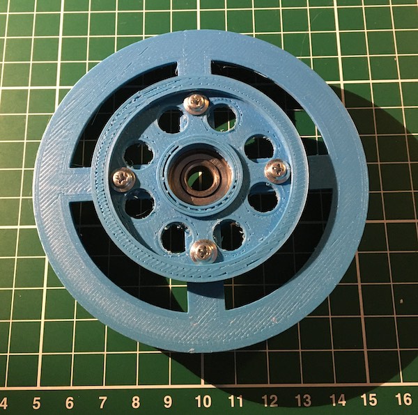
I have no wheels that I would like to use for this prototype. given the need for a 3D printed spindle for the belt, it might be best just to custom design and print the wheels as well. Then I can integrate the spindle for the belt, a wheel of good size (10cm diameter) and integrated bearing.  From the draft above on paper, I made this concept on OpenSCAD.


The green portion will be the wheel. It has a very wide hub designed to be fitted with a skate bearing. The Yellow portion will be the pulley for the belt. It will be screwed to the side wall of the wheel. The hub of the pulley is slightly smaller than the wheel to lock in the bearing.

3D Printing

Here are the results of the design, printed.  It took some test prints to get the resolution correct for the fine detail of the pulley.

Tilt - 3D printed wheel and pulley for balancing robot

Tilt - 3D printed wheel and pulley for balancing robot

Next Steps:


I am looking now for a piece of metal about 30+ cm long that I can fabricate into the leg of the balancing robot. These recycled printer motors need to have something thin and strong to bolt into. this can be achieved with 3D printing - but I think metal will be a better solution. 

Once the leg material can be found, I will be testing the pulley, motor, and tensioning. I have to be careful of any slippage of the belt.