I notice a very different design on the leg for the SEA and back linkage.
Showing posts with label EPFL. Show all posts
Showing posts with label EPFL. Show all posts
Friday, June 15, 2018
Robots from the Internet
I am starting to see more Compliant Quadruped Robots on the Internet. Here is the latest I have seen that was inspired by EPFL:
I notice a very different design on the leg for the SEA and back linkage.
I notice a very different design on the leg for the SEA and back linkage.

Sunday, June 10, 2018
Mojo - A Compliant Quadruped Robot (#4) - Back to the Spring
My basic requirements:
- be able to compress a 25mm spring down to 10mm
- not capable of pulling apart
- maintains it's x and y stability (keeps from bending)
- low friction
- easy to print
- easy to construct (minimal glue and clamping)
- easy to connect to the leg
Taking another close look at the EPFL leg, I see a fork on one side, and rod/piston holding the spring, and a coupling that allow the spring to compress and the piston to slide up. Sketched out it should look something like this:
  |
| EPFL Version top, drawing of new Serial Elastic Actuator bottom |
once I go through the CAD it the parts would look like this:
 |
| Parts drawn in OpenSCAD |
the fork is printed flat, the Piston/post vertical, and the end cap vertical. As I was designing it, I realized that I need to add the spring to the construction, so the post would have to be separate from the end cap and glued on, once the spring is added. The ring at the bottom of the post is not physically touching the post - I hope it prints!
I will need to glue the post to the end cap, after the spring is added then glue the fork to the ring. that is two (three) really big points of failure under stress, so there may be a few more iterations to reduce this risk.

My attempts to build this pointed out a few more flaws. Conceptually, it should all work together, however the implementation is proving to be problematic - too many glue points where the glue will be the only thing keeping the pieces together. The resulting engineering is undesirable. It will not be very reliable and will have premature failure. Back to the drawing board!

This new design has only two parts and no glue! The design is based on the shock absorbers on my "Hello World" Rover. the two pieces slide together and 'click' into place. The spring will site between the two. It should provide the stability and motion needed, although friction will be a problem (especially true since the printing process leave horizontal ridges). For all the work put into this part this weekend, I think it will do. :)

After a few iterations on the printer and tweaking the design a bit, I have a working linkage with 7.5mm of compression. Now, I have to think if my servos can manage this. Good engineering would have worked out all the forces before hand. But, for this hobby round, I am just tinkering. The springs are from recycled printers, I have a few to choose from. On the enhanced round I might consider different characteristics such as the amount of travel vs the force. But, this will do for now - I have 3 more for a complete set.
Learnings this round: a lot of 3D Printing and 3D Part design thinking. Difficulties in getting a high importance but complex part to be built.
next up ... servos!

My attempts to build this pointed out a few more flaws. Conceptually, it should all work together, however the implementation is proving to be problematic - too many glue points where the glue will be the only thing keeping the pieces together. The resulting engineering is undesirable. It will not be very reliable and will have premature failure. Back to the drawing board!

This new design has only two parts and no glue! The design is based on the shock absorbers on my "Hello World" Rover. the two pieces slide together and 'click' into place. The spring will site between the two. It should provide the stability and motion needed, although friction will be a problem (especially true since the printing process leave horizontal ridges). For all the work put into this part this weekend, I think it will do. :)

After a few iterations on the printer and tweaking the design a bit, I have a working linkage with 7.5mm of compression. Now, I have to think if my servos can manage this. Good engineering would have worked out all the forces before hand. But, for this hobby round, I am just tinkering. The springs are from recycled printers, I have a few to choose from. On the enhanced round I might consider different characteristics such as the amount of travel vs the force. But, this will do for now - I have 3 more for a complete set.
Learnings this round: a lot of 3D Printing and 3D Part design thinking. Difficulties in getting a high importance but complex part to be built.
next up ... servos!
Sunday, June 3, 2018
Mojo - A Compliant Quadruped Robot (#1) Intro
Every robot geek wants to have a robot dog! or cat! The idea of having a robot that can run and jump like a house pet is intriguing. The Use Cases of Search and Rescue, Estate patrol, finding my shoes, and eating weeds in my yard, come to the top of the head. And a herd of robot dogs would be a key addition to any "Totally Not Evil Robot Army"! This is my attempt to build one using Maker tech and Urban Mined parts.
The objective of this research is to explore how robotics can benefit from nature in the design and construction of the mechanics. One quickly realizes that the "static stability" of traditional robots, results in a very clunky design. For a robot to run and bound, it must have more dynamic properties. It must also find ways to conserve and use all of the energy produced by mechanics. This will introduce mechanical compliant systems to create flexibility and elasticity in the robot. BioRob was very successful in building the Cheetah Cub, and there are some good videos available of it walking, trotting, and bounding. BioRob has gone on to build a few new variants allowing for steerage, etc. In order to promote this concept more, it is time for the Makers to get involved and try to replicate the success and evolve the design if possible.
More to come...
Background and Inspiration
The most excellent robotic researchers at the Biorobotics Laboratory (BioRob) have been doing incredible research in quadruped robots. BioRob is part of the Institute of Bioengineering in the School of Engineering at the École polytechnique fédérale de Lausanne - EPFL. In 2013, they started publishing their results of their research in dynamic robots using compliant mechanics. This included the Cheetah Cub - a compliant quadruped robot, the size of a house pet.
 |
| Rendered Cheetah Cub - Biorobotics Laboratory, EPFL |
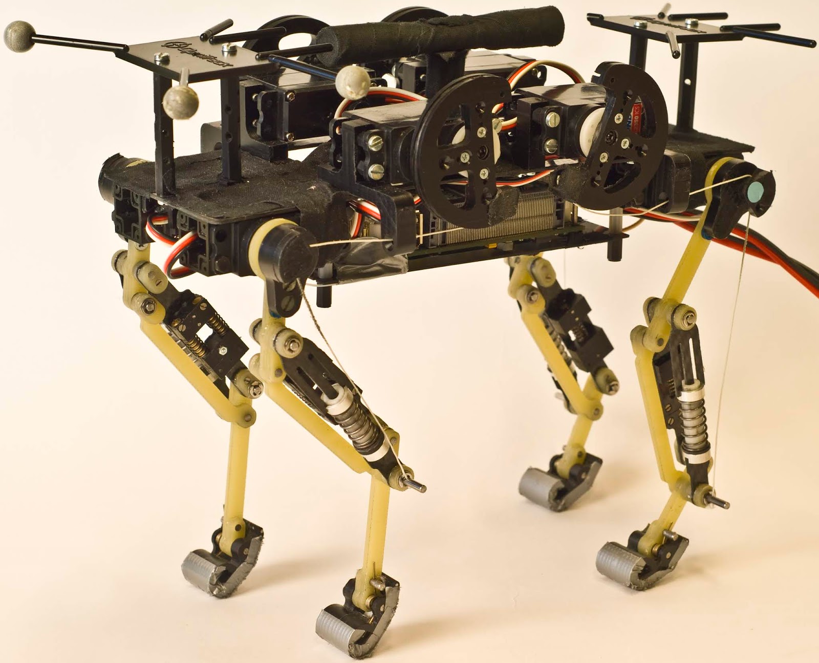 |
| Actual Cheetah Cub - Biorobotics Laboratory, EPFL |
Enter the Maker!
My next project was planned to be a Hexapod robot. But after reading about EPFL - BioRob's success and seeing the OpenCat project, I had enough inspiration to try for the compliant quadruped. Besides, I am really cheap when it comes to buying parts, a Hexapod requires 6x3 = 18 servos and a quadruped like this would only need 4x2 = 8 servos! (in theory). And dynamic is way more exciting than static!
 |
| A static 3D printed Hexapod leg vs the sketches of a compliant leg. |
So, off we go to build Mojo, my compliant quadruped robot dog. With Sketch pad in hand, I started to draw out what I have seen in the EPFL pictures. Paper drawings lead to my OpenSCAD design. Which I created my first draft on the 3D printer. For Mark1, I can only say that 1) "Do It" is achieved - the project is started and 2) It stands, sort-of, kind-of. :)
 |
| Mojo Leg mk1 - it does stand... |
Subscribe to:
Posts (Atom)