The Robots are coming! Are you ready? Now is the time to build the (Totally Not Evil) Robot Army! This blog creates, builds, and explores the personal 'Making' of robots. Enjoy!
Every project reaches that pivotal moment when progress halts, and the creative spark seems to fade. For Mojo5, that moment has arrived. This little robot has encountered a significant challenge in the design of its abductors. The servos have developed excessive backlash, compromising its ability to stand and walk effectively.
In an attempt to resolve the issue, I removed the servos and installed a 'static' gear to lock them in place. Unfortunately, this fix didn't fully eliminate the backlash, and the problem persists. Addressing this issue would require a major redesign, far more extensive than initially anticipated.
With a heavy heart, I’ve decided that it’s time to retire Mojo5. But as with all endings, this marks the beginning of something new. Long live Mojo6.
After the first prototype testing, it was evident that the 'drive gear' was slipping. This is the gear that is directly connected to the 3D printed gearbox. The gearbox itself may have some backlash (flex), but otherwise the system was pretty tight. It was just that the pressure from the leg mechanism was causing the gear to slip.
Here is a short video of the slippage
The fix to this turned out to be a simple change from a regular spur gear, to a helical gear. (the gear with a slant)
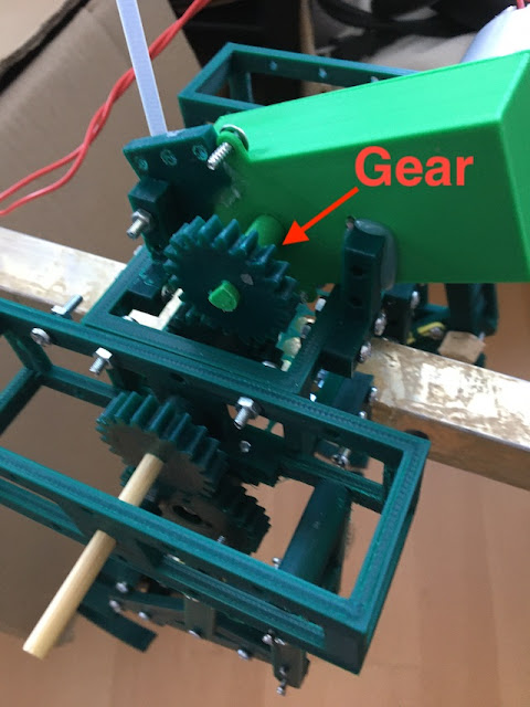
here is the original gear on the gearbox:
robot-runner with original spur gear
and the new CAD model (OpenSCAD)
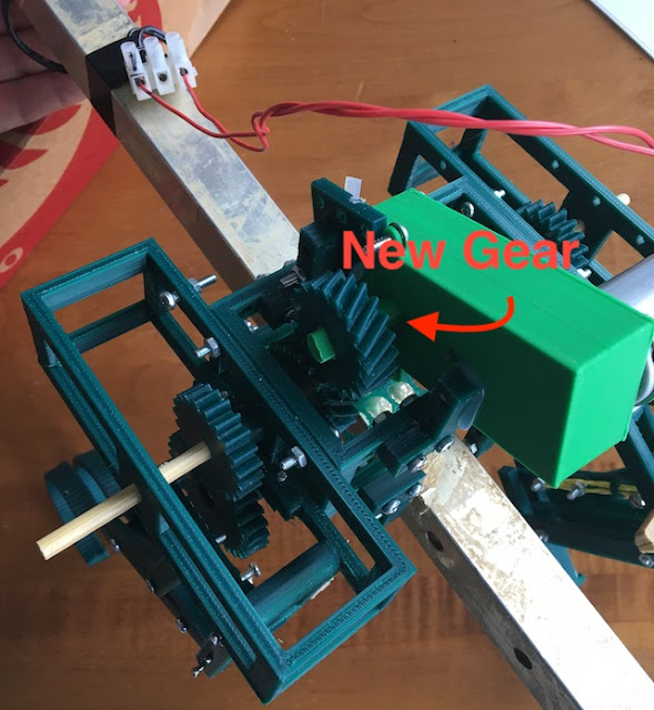
This gear design has additional surface area touching in the teeth of the gear. This is all that was needed to improve the operations.
Helical gears are one type of cylindrical gears with slanted tooth trace. Compared to spur gears, they have the larger contact ratio and excel in quietness and less vibration and able to transmit large force. A pair of helical gears has the same helix angle but the helix hand is opposite. (hkgears.net)
New gear:
robot-runner with helical drive gear
Second prototype test: Much better
All and all, I will pause this development for the moment. The mechanism is not performing as well as I would hoped for this point in time. I may return to the design. But, for the time, I am thinking more about a more functional base robot - back to MinOne.
Mojo4 has regressed in its ability to shuffle across the floor, unfortunately. This regression could be due to various causes. I have some concerns over the battery current and the condition of the battery given the temperatures and current. It is also obvious to me that the 'Franken-Prototype' nature is having an impact on the testing of the robot. It seems that the franken-prototype has taken the design as far as it can go, and an upgrade is necessary to continue forward. on to --
Mojo4 - Robot is a mess, it needs a better frame or chassis
De-Frankensteining
the majority of the robot is currently built with reused pieces. The is due to the focus being on testing how viable the legs will be for walking. Having (somewhat) proved this, the next steps need to have a more reliable robot platform. First on the list is to secure the 4 leg units with a better frame or chassis. I would like to do this in a way that any new parts, will be used in the future robot (as much as possible).
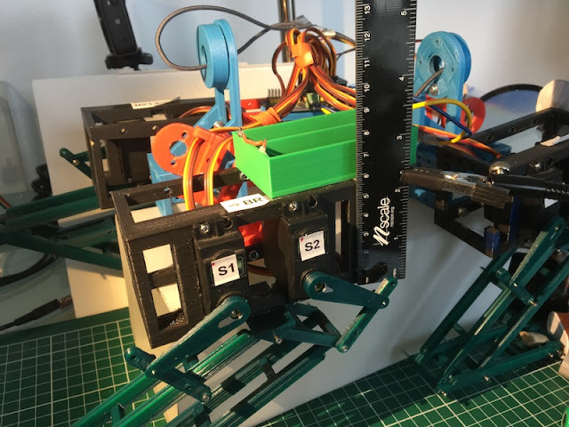
I will create some Frame Sections that will separate the leg modules, a provide a more stable chassis. Notice how the right side leg modules are actually not aligned with the rest of the robot - this will certainly have impact to the ability to have a precision walk.
Backward compatible - should not exist as a design constraint of a NEW robot in the prototype stage! But the question comes to mind. In order to only build the parts I need, I would need to ensure that the new replacement part fit the same configuration of the existing parts. This mean that the new part is 'backward compatible' with the older part. This, however, wold be a design sin at this stage. It would limit the innovation of the future robot, tying it needlessly to an obsolete part.
One note, since my parts tend to have regular 10mm spaced holes for M3 bolts, it does provide a lot of reuse potential. Unfortunately, i found that my previous designs, I was less concerned with 'standard' parts; therefore many of my old parts do not have regular dimensions (around the rounded cm values). This has limited my ability to reuse. Going forward I will be more careful to make sure parts I design fit into somewhat regular dimensions.
Frame Section:
I have designed a frame part that will help construct the prototype, while also being a useful part for the future build. This Frame Section is a box of 10cm x 6cm x 4cm dimensions. It will have M3 holes on the outside and a basic 'floor' for holding components (battery box, or Micro controller).
Frame Section - useful and reusable building component
If I print out 3-4 of these, then I can replace most of the frankenstein-prototype parts used to hold the leg modules in place. This should provide a more robot platform for testing the basic gait and servo strength.
[This is an older post that did not get published. It describes the last steps taken on Tilt! This was also part of the motivation for building a gearbox for recycled printer motors.]
Tilt! Balancing Robot - testing configuration
After some time with "communication failure", I sorted out some loose connections and got the initial prototype working! All hail the Cargo Cult Programmer! (need to to write more of a story on this one I think.)
Torque and the Printer motors. The large gear ratio with the belt pulleys is working. The wheels are turning and it is just enough to suggest that there is an attempt at ballance. At least this seems to be true in one direction.
12V Testing. Some testing with the 'power' of the motors or how easy it is to stall the motors is *not* very encouraging. with only small effort, I can stall the printer motor. This is with 12 volts of power - certainly at the lower end of the rating for these motors. Attempting more power up to 18V will be worth the test, although my built in battery bank only supports 12v. (thinking) 18V with a RC battery might be feasible.
18V Testing. By connecting the robot up to 'shore power' (tether), I bypassed the onboard battery and supplied 18V to the motors. The robot was a bit more responsive, and the issue became more clear. Instead of stalling, the motor caused the belt to slip. In either case, a re-design of the motor-drive-wheel system is in order.
Another aspect is to reduce the gear ratio and see if less torque is an option. This could be done by printing new pulleys. but what I sacrifice in torque and gear contact - may manifest undesirable slippage on the pulley. Given the results of the 18V testing, the best option will be to use a gearbox to increase the torque of the wheel, and reduce the speed/impulse of the motors.
Next Steps - The gearbox for printer motors is already in progress. The initial results of that design are very positive. I will be replacing the motors in Tilt! with new gearbox driven versions.
Perhaps this takes a little more thought than I first expected. I am trying to build this robot using scrap parts from printers, standard components, and in this case the bearings and axels from a pair of inline skates. WELL... that lead to some issues with the wheel mount. Today, I am re-engineering this design and building the wheel mount.
First attempt to test the motor, belt and pulley
Here is are the parts. I was trying to rig them up to quickly test how much backlash I would get from the old printer motors and belts. However, the axel and wheel were so wobbly that I could not make it work. (In addition, my plans to use a piece of scrap pressed steel to attach the motor are dashed - I do not have the necessary tools to cut large holes in the steel. so back to the 3D printer!!) Also, you will see, I am re-using the printer's belt drive. This is about 70cm in length.
Wheel, bearing, and axel from an in-line skate wheel
The design problem is how to use the already dimensioned Axel and Bearings. Since I am reusing this part, I must work around it's length. It is longer than what I will need. In addition to this concern, I will need a way to secure the axel to the base and wheel mount of the Tilt robot. This is not typically a problem with balancing robots that us stepper motors since they have more direct control of the wheel. However, I firmly believe that the weight of the robot should not be directly applied to the motor. Thus I am using bearing and separating the load from the motor.
Checking the alignment (modulus) of the belt and the 3D printed pulley
I sketched out the arrangement of the bearings and spacers and axel. It is necessary to 'plug' the bearing into both the wheel/pulley. While redesigning this aspect of the wheel, I took the time to inspect the belt to make sure the pulley's teeth aligned with the belt. This is based on the modulus I calculated. It seems to match.
On the frame side, i repeated the bearing housing, creating a mount that holds the bearing but provides freedom for the axis. I am sure this will have another review in future robot designs. After printing, I will test out this new design.
Tilt - Wheel base design (in red) - OpenSCAD
For the frame, I am still unsure what materials I will use for the 30cm between the wheel axel and the motor. since I do not know, yet, I designed a simple 3D printed frame with 10mm separate holes for M3 bolts. With this design I will have the flexibility to use anything, and just bolt that to the structure.
Next Steps:
The next steps are to print out the new design and assemble a single wheel for testing. this structure will allow me to clamp the wheel to the table and test the tension on the motor. I will be looking at how much backlash or slipping the belt will have.
The next physical design step will be to find a way to connect the motor mount to the wheel mount.
Update:
Here is the printed wheel mount. The scrap steel would not work very well. I currently lack the tools to shape it and bore holes through to attach to the motor mount.
I did have two rods of medium length from printers I salvaged. With the ability to print out parts, I printed a rod mount. The mount is adjustable using the rubber rollers that are already on the steel rods. (now i just need two more for the other side!)
A workable prototype for one side of the balancing robot
Milli is a bio-inspired Millipeded Robot and today's blog entry is titled: FrankenWorm! Rapid Prototyping The best way to "learn quickly - fail quickly" is to using rapid prototyping techniques to test out ideas quickly and identify potential and real points of failure, design needs, and radical improvements. Three-D printers are great for taking ideas and making them solid. An even faster way of rapid prototyping is "Frankenstein Prototyping", where the initial prototypes are built by using parts from other projects. In many cases, you just grab the part that is close to what you need and fasten it to the build.
Frankworm! Franken-prototyping the WildWorm Drive
Today, I am Frankenstein prototyping the WildWorm with 3D parts left over from previous projects. I wanted to quickly see if the rotating helix is going to be able to move the track treads of the WildWorm drive. what is in the discarded print bin?
Motor frame - one of the chassis from the original Mojo
Battery holder - from an old RC car and RC Rover project
Motor holder - initial WildWeasle tests - holds a 'recycled' printer motor
Motor spindle adapter - from initial Centi tests
Helix Mount - Cam variation from the Mojo2 (he walks!) project
Horizontal Stabilizers - linkages from original Mojo project
Stabilizer linkage - v0 print of WildWorm track
...and this is why I don't throw away old 3D printed parts.
After finding the parts in the bin, I connected them all together to set up my initial tests. I just used quick fastening methods, tape, hot glue, twisted wire, and screws. It is meat only to learn what works, and what does not!
Can you identify the parts in the picture??
WildWorm prototype test - Franken Prototype
Test Results
I ran the first tests with a weak battery pack, just under 5V DC. This was attached to a recycled printer motor that is rated 9-12V (I believe). I thought the motor had plenty of torque to rotate the helix without beating the assembly to pieces. -which was important at this stage.
The video shows the results of my initial testing.
First of learnings, yes this worm drive concept is feasible. The underpowered motor is just barely turning the helix, but the rotation is consistent enough to move the treads. The stabilizer will need to be tightened up to keep the tracks in a steady horizontal position. and the helix will need to be smooth, as well as the inside of the treads, in order to reduce the internal friction and sticking.
This test only proved that the motor with stabilizer will move the track in the correct motion. There are a lot of design learnings available, now I can iterate on these ideas and go for the next set of testing.
Mojo can now walk! Numerous testing and enhancements including new feet/"paws", stronger 'tibia', and gait positioning have led to the first successful walk. See the video below.
Leading up to the successful walk, here are the issues that had to be resolved.
Back side of Mojo2 - right hind leg is translationally forced inward. The new button - switches between 'walk' and 'stand' is very useful!
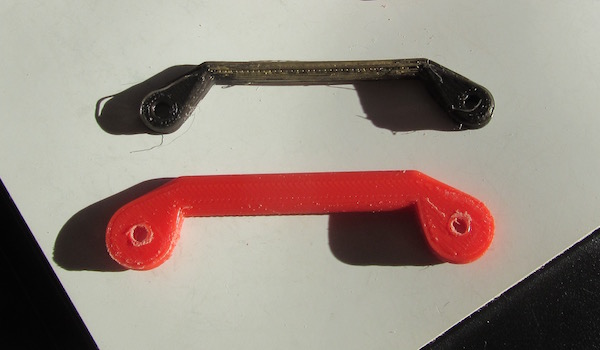
New tibia, stronger with larger hinge one of the biggest issues was the amount of "translational" movement of the leg. This means that the leg was able to be bent under the robot very easily by the forces put on it. It is caused by the looseness and flexibility in the leg and its joints. tightening the screws holding the linkages together helps - but increasing the size of the hinges would help more. In addition, creating a tighter screw hole will decrease this flex. In the process of doing this, it became evident that the 'tibia' linkages were highly flexible - they twisted quite easily. The fastest fix to this issue was to make the tibia thicker and reprint the linkages.
New Tibia - larger, much less torsional flexibility - same size 70mm
With all (8) new tibia installed, the leg structures are significantly more ridged. this prevent the bending inward as seen in the first part of the video. you can easily spot the new tibia, since they are now red instead of back. New Paws with a more compliant capability The Paws have been replaced in the latest video sequence. you may notice that the robot is resting on the new compliant, spring loaded, paws. This should add to the compliancy of the robot as well as provide more traction to the pull of the leg. However, it is evident in later tests, that the compliant paw requires the leg to lift more in order to clear the ground surface. This is a problem yet to be addressed.
New Distal "paws" or feet, now compliant with effective springs.
Gait Sequence The gait sequence is actively being adjusted. In the latest runs, the hind legs have been moved back by 10 degrees. This new posture has improved the stability, and may have been directly responsible for the first successful steps. However, there are many many variable in this dynamic problem. Tuning one or two often leads to another instability. In the process of adjusting the tibias, the SEA on the rear hind leg broke. I printed out new one and used a different spring. The k-constant value of the springs varies by spring. This creates another uncertainty in the tuning of the legs. Having a reliable means to determine the 'k' of the springs would help in creating a consistent behavior across each leg. An adjustable SEA would do wonders.
Broken connector at top of SEA
Getting it to repeat To be honest, some minor adjustments after the successful test, have created a newly unstable robot. Tightening some of the joints can result in the robot starting to 'moon walk'. This illustraits how sensitive the robot currently is to small changes. More improvements into tuning and adjustment will be needed to start getting consistent results. But that is what makes this fun. Right? :)
Another failure: the eye screw suffered metal fatigue being screwed in to a small hole. This can not be removed, thus requiring a new part to be printed.
The walking trials of Mojo 2.0 are continuing... It was evident that the lack of balance of the robot was due to the starting leg positions being too far back, creating a tilt forward from the lack of support for the center of gravity. This could be addressed by changing the starting angles forward.
Stability could also be increase by elongating the robot. Luckily, the mojo2 design provides for just that capability. A spacer of 35 mm was added to the waist of the robot.
New "longer" Mojo2
with the new longer version, it was possible to start it walking. During the trials, the robot fell over on it's side and broke a "hip". This part was known to be an issue as it was printed with a clogged 3D printer nozzle. Luckily, it only required 45 min to print a new hip, and about 15 min to replace it.
Broken Hip
once back together the gait examination continued... it became clear that Mojo2 was walking backwards - because it was programmed too! :0 The coding has be reworked and the servos reconfigured. Mojo is soon to be walking forward, I will have video in the near future. paw stability is now the biggest issue. more to come!
Mojo 2.0 - A Compliant Quadruped Walking Robot "Dog"
I am still investigating the best leg design for Mojo - The compliant quadruped walking robot. It is clear from the videos that perhaps the legs are "too compliant". The springs are showing some compression, even as the robot stands. Also, in the configuration, the robot can not handle the weight of the battery without further compression.
Mojo - The Compliant Quadruped Walking Robot - with sexy robot legs
I believe when the knee servo pulls the leg up, the robot is not gaining much more additional compression. In addition, when the leg is moving back in the gait, the leg also compresses. So, it seems, I will need either stronger/tunable springs or perhaps a 'less compliant' compliant leg.
So, we iterate through a different design! The new design that will allow for the leg to be pulled back, with out compliance. But, still have the ability to be compliant when the knee is flexed and absorb some ground shock.
Straight legs with "knee joint" - 3D printed
The new legs are straight, with a "knee cap", and the Serial Elastic Actuator (SEA) is located on the back. Unfortunately this design does not have much in aesthetic appeal. - They are ugly!!
Mojo - A Compliant Quadruped Walking Robot - now with "knobby knees"
Hmmnnn... I am not sure if I like this tangent in the design. The knees perform better in the standing position. Walking is still very unstable. The new actuators do not have much clearance Unfortunately, this design experiment did not yield good results! Such is prototyping.
The "Fail Lizard" is alive, and crawling around so be careful. no worries, it is 'Totally' not evil! It just looks that way. :)
From the video you can see that I have been working on some different robot parts like GRIPPERS! I thought it would be interesting to see if I could create something that could move, with only two servos. That is how Fail Lizard came about.
Unfortunately, there was a mis-hap with the polarity of the power source. Learning point, if you have your servo power cross wired with the ground, you will start to smell the smoke. once I found my mistake, I was able to quickly rebuild the Fail Lizard and take it for a crawl. Despite being thrown together very very quickly, it was able to 'Autonomously' crawl/drag its self around. At the same time, gnashing it's gnarly (totally not evil) grippers.
Fail Lizard casting a long shadow
Fail Lizard is certainly a robo-hack, it was created for the primary purpose of creating a crawling gait using only two servos, one to 'twist' the back and the other to 'twist' its legs. This seems to work fairly well, the video segment had no tuning of the gait at all. AND the secondary purpose was to put (totally not evil) grippers on something!
Build your own Fail Lizard:
- 3D printed parts, including reused Mojo Chassis
- 3 servos: Grippers, Legs, back-twist
- Arduino Pro Mini, breadboard, jumpers, clothespins(!)
- Intentionally heavy USB power bank, zip tied
- all the love that only an inventor can give to an otherwise ugly beast! :)
I also learned that despite the smell of burning servos, the servos only had minor damage and with a little solder I was able to put them back together.
Smok'n Servo just needs the power lead re-soldered
So, actually the Fail Lizard resulted in some good experience in servo debugging, USB connector wire (why does it seem that they are always upside down?!?), dynamics of a crawlers, and some sweet new grippers!
Finally, a few new upgrades. I have been watching tutorials on ShotCut, and was able to produce a little more professional video. Thanks MechaLion for the support! And thanks to Gunnar Olsen for providing some cool music for the Fail Lizard to crawl to. :)
AND we now have the domain totallynotevilrobotarmy.com !!
This week has been mostly errors in the 'trial and error' school of invention. But, alas! that is part of the process. Mojo did get a new chassis and spent some time moving the components from the previous version to the upgrade. Important features include:
additional separation of the knee and hip servos
roll bars and front/rear bumpers
more room for wiring and 9V battery
"learnings" from the previous design/print - 7cm spans worked with better design
room for future proto board, LEDs, Buttons, and Switches
He is a bit longer, I had some concern about effects to the gait. but, the servo separation will allow for longer gaits.
Mojo - New Chassis, improved SEA, same Compliant Quadruped
Currently, It is still going through variations on the gait sequence. The new Lateral Sequence is promising. I increased the gait length and speed up the swing, however this is had a negative impact to stability. I will need to rework the gait, but I think the fast swing is important. Might also be worth trying a very very slow gait to start. Smokin' Servos! The Fail of the Week was the secret "Lizard" project. I was kicking around ideas about a very basic crawler, something with two 'legs' that moved and drags the bot along. it would have just 2 degrees of freedom. In addition I added a pincher to the front, just because it was around. the pincher, takes away from the Lizard motif, but its cool. Cool or not, I worked on a Minimal Viable 'Prototype', with servos stuck together and reused the old mojo chassis. I wried up a 5v, 2A power bank, a Arduino Pro Mini and the servos. A few lines of Arduino sketch, and I thought I was ready to go. Unfortunately, I got no movement from the servos. I checked the wiring, all good, code up loading, check, code running, check. Odd smell? check! When I picked up the bot, I noticed that the servos were 'Fire Dog Hot' and smelling cooked! I am pretty sure they are toast now. This I did not expect. Everything was 'safe', more debugging needed!!
Fail Lizard!
Back to the drawing board for the 'Fail Lizard' - might as well make it a new beasty! The down side of mechatronics, is that you typically burn out boards, servos, and sensors - in addition to hanging code. Fail Lizard brings my servo bone pile up to 5 servos!