Showing posts with label Video. Show all posts

Sunday, April 27, 2025

PolyMap & Minone: First Test Results (#4)

Simple SLAM Robot: Initial Tests with PolyMap and Minone

Both the PolyMap mapping platform and the Minone robot have reached a level of functionality sufficient for their initial tests together. The early results are exciting, though clearly revealing room for improvement—exactly as anticipated!

Here's a video capturing these very first tests. Having this visual documentation will greatly help us track the robot's progression as we refine and improve the SLAM capabilities.

Overview of the First SLAM Tests

These initial tests show how well the mapping system, PolyMap, works together with Minone, a very minimal robot platform that is built around an ESP32 microcontroller. Minone, equipped with only a single ultrasonic sensor, navigated a confined hallway environment. All communication between the robot and the mapping software was successfully managed via MQTT, demonstrating effective real-time integration.

Minone, alone in the hallway.


In this test setup, Minone was in a hallway out of my vision. My phone was recording its movement. I sat in an adjacent room behind the door and was instructing the robot through the visualization. Commands were sent using MQTT to the robot and telemetry and map data was returned as previously discussed. In this test, I did have the reassurance that it was working, as I could hear the motor movement down the hallway.

Mapping Process and Key Observations

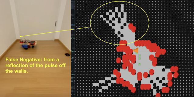
The PolyMap visualization provided live feedback during the tests with telemetry and maps. On the map you can see:

  • Robot position was clearly indicated in orange.

  • Obstacles detected by the ultrasonic sensor appeared in red.

  • Unexplored areas remained marked in black.

  • Telemetry shows the Pose (X, Y, Θ) and state: Manual

PolyMap Viz April 2025 (Totally Not Evil Robot Army)

The visualization effectively demonstrated the system's ability to build a cohesive map from successive sensor readings. However, the tests quickly highlighted significant limitations associated with relying on a single ultrasonic sensor:

  • False negatives: The sensor occasionally failed to detect obstacles, particularly when encountering oblique angles. The pulsed ultrasonic signal reflects off the surface and does not return to the sensor, the device times out waiting, and returns a long distance (in this case greater than 170cm)

  • False positives: There were numerous instances of the sensor incorrectly registering obstacles due to noise and sensor inaccuracies. This could be due to echos, but otherwise indeterminate (for me at this time).

Minone, False Neg due to Reflection in corner.

These limitations underscore a common challenge when using ultrasonic distance sensors. In simple SLAM test, there were no special filter applied or sensor data management used. This is a clear direction for improvement in the next code iteration.
Initial Conclusions and Immediate Next Steps

The primary next step is addressing the significant number of false positive and negative readings produced by the ultrasonic sensor. To tackle this challenge, the mapping algorithm will transition from a basic binary representation (occupied/free) to a probabilistic occupancy grid, employing the log-odds methodology. This approach should significantly reduce the influence of sensor inaccuracies by statistically weighting sensor readings over time.

Looking Ahead: Introducing Mintwo and Exploring Swarms

Future development plans include building an upgraded version of Minone: the Mintwo robot (?!?). This iteration will be enhanced by incorporating multiple IR time-of-flight sensors, dramatically enriching the data quality and robustness. The improved sensory capability of Mintwo will not only enhance individual robot performance but also lay the foundational work for exploring coordinated behaviors and swarm robotics, leveraging PolyMap’s scalable and distributed architecture.

Stay tuned as we continue to iterate and enhance both the PolyMap platform and our expanding army, ehr.. family of robots!

Sunday, April 13, 2025

Minone – Getting the MV#Robot to Stable (#3)

Minone – Getting the MV#Robot to Stable (#3)

It's been a busy stretch since the last update! Many improvements, refactoring, debugging, and learning sessions have pushed the Minone MV#Robot toward a more stable and robust platform.

Code: Structure and States

Most of the recent effort has been dedicated to fleshing out software needed for remote operation. The robot's codebase has significantly expanded, particularly around the command structure. I've implemented a state model to handle essential high-level states:

  • Standby: Robot awaits commands—especially useful after a reboot, allowing manual verification before resuming tasks.

  • Manual: Direct control, crucial for immediate testing and remote operations.

  • Autonomous: Fully independent operation. Future enhancements will include advanced exploration strategies, frontier search, and swarm coordination.

  • Pause: Temporary halt; currently, the robot resumes directly into Autonomous mode.

  • Error: Safety state activated by unexpected issues.

High-level state changes are now managed via an MQTT subscriber, enabling remote state-level commands. In Manual mode, the MQTT listener also accepts individual task commands for immediate execution.

To efficiently handle robot actions ("tasks"), I developed wrapper code that allows manual triggering for debugging flexibility. Additionally, during Autonomous mode, the Robot's Agent autonomously generates tasks, utilizing the same task infrastructure.

Precise Movement Challenges

One aspect differentiating a true robot from a toy or simple remote-controlled device is the ability to move precisely. For mapping and SLAM purposes, it is crucial to know exactly where the robot is and its pose. To understand how much a motor has turned, an encoder is used to 'count' the amount of rotation. Minone uses encoders that are built into recycled Roomba wheel modules I am using. Knowing the number of pulses per rotation and wheel dimensions allows precise odometry calculations—determining how far the robot moves or rotates.

Initially, Minone exhibited incorrect odometry during turns. Calculations seemed accurate—asking to move 10cm resulted in software reports of 10cm—but the physical movement was actually 20cm. This discrepancy first appeared in rotation measurements, which were exactly half the physical result. At first, I assumed calculation errors were related to the complexity of the turn calcuation. The wheels are rotating in opposite directions and you must factor in wheelbase dimensions. A quick patch improved turn precision slightly, but the underlying movement issues remained.

Digging deeper revealed encoder pulse counts were half the expected values. Although the very specific 508.5 pulses per rotation was correct, I initially misunderstood that this value included both rising and falling edges of the encoder's square-wave pulse. A small adjustment resolved this completely:

// --- Encoder Setup ---
void setupEncoders() {
  pinMode(LEFT_ENCODER_PIN, INPUT_PULLUP);
  pinMode(RIGHT_ENCODER_PIN, INPUT_PULLUP);
  attachInterrupt(digitalPinToInterrupt(LEFT_ENCODER_PIN), leftEncoderISR, CHANGE);
  attachInterrupt(digitalPinToInterrupt(RIGHT_ENCODER_PIN), rightEncoderISR, CHANGE);
}

Switching the interrupt trigger from 'RISE' to 'CHANGE' allowed counting both edges. Problem solved! Recognizing this resolved earlier incorrect adjustments, making robot turns and movements significantly more accurate—not perfect yet, but sufficient for this prototype stage.

A cautionary note on AI-assisted coding: Unfortunately, my AI coding companion missed this nuance, underscoring the continued need to have some knowledge of what you are working with, both in code and hardware. The AI repeatedly suggested using 'RISE,' which cost significant debugging time. Only through examining code from other experienced developers—a big shout out to Bill at DroneBot Workshop—did I discover the proper approach.

Coordinate Systems & Rotational Model

Choosing a coordinate system for your robot is critical, impacting navigation, mapping, and visualization. Coordinate systems aren't always the simple math we learned in high school (traditional X/Y axes). You must consider the Z-axis for rotation and eventually 3D mapping, plus how your robot’s "frame of reference" relates to mapping standards reference. Surprisingly, industry standards differ significantly from basic Cartesian assumptions.

I selected a right-handed system (X-forward, Y-left, Z-up) for the robot frame, aligning with robotics conventions used in platforms like ROS. Positive yaw indicates counterclockwise (left) rotation, while negative yaw indicates clockwise (right) rotation. Though initially counter-intuitive, maintaining consistency across code and system interfaces is very important.

Downstream, the Map Manager and visualization components must translate these standards, especially when interfacing with game engines like Godot, which often uses a different convention.

Minone 11 APR 2025 - MV#Robot

Hardware Improvements

The prototype hardware has also been improved in this iteration. Adding a level shifter stabilized communication between components with different voltage domains. To safely power the ESP32 independently, I now directly use a clean 5V source from a power bank rather than the L298N's regulator.

Currently, the robot remains on a breadboard— a big messy rats nest of jumper wires. Future builds will transition to a safer proto-board with robust connectors for stability and better cable management, reducing risk of havoc from loose connections.

Demos: Seeing the Progress!

Here are short videos captured during the build process. The first demonstrates basic movement and scanning routines without intelligent decision-making:

The second video shows progress after foundational movements were implemented but before odometry corrections—movements rely on timing rather than accurate angle calculations. Since filming, accuracy has significantly improved!


Thanks for following along! The Minone MV#Robot journey continues—iterate, iterate, iterate!

Sunday, June 23, 2024

Mojo5 - Enhancing Performance with More Powerful Batteries (11)


Mojo5 - with power bank battery

Welcome back to the "Totally Not Evil Robot Army" blog. In this 11th installment of the Mojo5 series, we’re going to dive into a crucial aspect of building robust quadruped robots: using more powerful batteries to drive hobby servos. Specifically, we'll explore how increasing the available amperage and voltage can significantly improve the performance of underpowered servos and the considerations needed to ensure safe and efficient operation.

The Problem with Underpowered Servos

Building a quadruped robot like Mojo5 with cheap hobby servos often leads to performance issues. Many of these servos, such as the MG995, are slow and lack the torque needed for dynamic movements. Even with a 5V power supply, these servos can become wobbly and unreliable, especially under load. This is where upgrading to more powerful batteries comes into play.

The Limitations of the Original Power Configuration

Initially, Mojo5 used a 5V 12000mAh power bank. While this power source had a high capacity, it was limited to a maximum output of 3A. Given that the MG995 servos have a stall current rating of up to 3A each, the total current demand for the robot could easily exceed 20A during peak operation. This significant shortfall in available current was a primary cause of the robot's poor performance.

Upgrading the Power Source: LiPo Batteries

Based on previous discussions and experiments, we found that using a more powerful battery can drastically improve servo performance. Upgrading to a LiPo battery with a 2200mAh capacity, 7.4V voltage, and a 50C discharge rating provides the needed boost. This battery can supply well over the 20A needed by the servos, addressing the current limitations of the previous power source.

Considerations for Over-Volting

  1. Risk of Burnout: Exceeding the servo’s voltage rating does carry a risk of burnout. However, anecdotal evidence suggests that slight over-volting is generally safe if monitored properly. Implementing a voltage regulator could limit the current capacity, which might be counterproductive. In general voltage regulators on servo power sources are not recommended.

  2. Separate Circuits for Different Servos: For servos with lower voltage ratings, such as the MG90 (max 6V), consider creating a separate circuit to avoid over-volting. This will add an additional circuit which can be problematic. For my experiments with Mojo5, I used the same circuit.

Practical Application: Experimenting

Initial Setup

  1. Battery Connection: Connect the 7.4V 50C LiPo battery directly to the power bus of the PCA9685 servo driver, bypassing capacitors and regulators. This setup ensures the servos receive power directly.

  2. Handling Large Wires: Safely connecting XT-60 battery connectors and their thick 12 AWG wires to smaller electronics is challenging. Using a bare copper PCB or prototyping PCBs with multiple copper lines can provide a more robust connection. Soldering all wires together is an ugly but space-efficient solution.


Not Recommended!


In this experiment, I took the short cut and soldered the large wires directly in to a dupont connector. The connector was connected directly to the servo bus. This is not a recommended practice! I better connection with larger wires is recommended. In this particular case, as long as all of the servo motors do not stall, then only brief seconds of +20A current would be expected.  Current greater than 7A for sustained periods of time would destroy the connectors.

Experiment Results

After connecting the 7.4V battery:

  • Servo Performance: There was a noticeable improvement in servo actuation. The MG995 servos operated better, with no immediate burnout.
  • Heat Management: Monitoring the temperature of connectors and wires is crucial. Using a finger-test method (keeping fingers on components for one minute) can help identify safe current levels. If components become too hot to touch, reduce the current.

To visualize the improvement, I have embedded a short video showing Mojo5's performance with the original 5V power bank versus the upgraded 7.4V LiPo battery. Notice the difference in servo response time and stability.


Long-Term Solutions

While the initial experiments are promising, long-term solutions require more robust hardware:

  1. Custom Servo Driver Board: Developing a servo driver board with better connectors and thicker traces can handle higher currents more efficiently. This would replace the PCA9685 board, which is not designed for high current loads.
  2. Current Monitoring: Implementing current measurements and safety features like e-fuses can prevent overcurrent situations and protect your components.

Conclusion

Upgrading to more powerful batteries can significantly enhance the performance of underpowered servos in your DIY robots. While there are risks associated with over-volting, careful monitoring and proper hardware can mitigate these risks. As we continue to push the boundaries of DIY robotics, sharing these experiences and solutions will help us all build more capable and reliable robots.

Sunday, April 28, 2024

Mojo5 - Inverse Kinematics in Motion (#9)

I've recently implemented an inverse kinematics (IK) solution to enhance the precision and control of robotic leg movements. Our primary experiment involved programming the leg to execute a simple rectangular movement pattern, with a focus on maintaining accuracy and consistency. Here, I will share some intriguing geometrical observations and challenges we encountered.

Intended Path and Test Setup

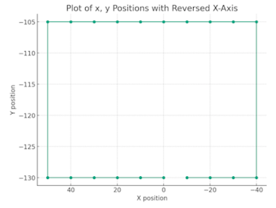
For this test, the robot leg will start in the (0,-130) position. Moving clockwise, It steps backward (in my case more positive, note the inverted x axis) to the (50, -130) position. Next up by 25mm to the top. At this time I use a different z position, but it is hard to see. the motion continues around in a rectangle ending at the start.

Planned path for simple gait test. starting at the center bottom

Video Analysis

In the bolow short video, the robot steps through the gait path. The leg is mounted above the table and horizontal to the table, not in a typical robot position. I have traced each step of the path, with a small dot at the end of the foot.


As seen in the video, the motion lacks the expected precision, influenced by several factors:

  • Fixture Stability: The fixture holding the leg is unstable, contributing to erratic movements.
  • Manual Marking Inaccuracy: Yellow dots indicating key positions were marked by eye, leading to imprecision.
  • Servo Calibration: The calibration of the servo points was approximative. At a setting meant to be 90°, the actual angle could range between 85-95°.

Geometrical Challenges: The Skew Issue

One of the more fascinating issues we observed is the skew to the left when the leg is raised vertically. This skew is likely influenced by the constraints of the 'solution space'—the range within which the actuator operates. As a result, there is a slight warping effect in the grid area over which the leg can move.

Mojo5 Inverse Kinematics - geometric skew

Implications of the Skew

  • Motor-Driven Distortions: The two servomotors, designed to drive the leg in specific rotational angles, do not guarantee a perfectly perpendicular alignment of the movement path. This introduces a mathematical distortion in the intended trajectory.
  • Impact on Gait Creation: While this skew does not necessarily hinder the robot's ability to perform meaningful gaits, it highlights an essential aspect of robotic movement—geometric imperfections inherent in mechanical and software solutions.

Further Research on the Mapped or Solution Space

The space in which the robot can operates can be understood as the geometric area or volume within which the robot can effectively reach and manipulate objects. This space is defined by the following:

  • Reachability: Determined by the length of the robot's arms and the range of motion of its joints. The maximum and minimum extents of each joint define the outer and inner boundaries of this space.
  • Compliance: In the context of SCARA robots, the vertical compliance allows for certain movements in the vertical plane within the workspace. This selective compliance helps in absorbing forces during tasks like assembly, where vertical give is beneficial.
  • Kinematic Constraints: Defined by the robot's mechanical design and the kinematic equations governing its movements. These constraints delineate the paths and patterns the robot can execute.
  • Control Resolution: The precision with which the robot's controllers can position its joints also defines the resolution within the mapped space, influencing how finely the robot can maneuver within its reach.

Certainly a very interesting area of study in robotics!

Friday, March 29, 2024

Mojo5 - Video Update, Next IK (#6)

The development of Mojo5 steadily progresses, we've put Mojo5's new leg design through its paces. This latest test, captured in a YouTube Short, showcases a significant enhancement in the design, specifically in the addition of a 'yaw mount'. Although the abduction servo—responsible for the 'yaw' movement—is not operational in this iteration, the primary focus was on the leg's up/down movement capabilities.


One notable improvisation was the use of a hastily clamped mount to a flexible support. This setup was crucial in providing the freedom of movement required while still managing to lift a weight of 370g. It's a testament to our iterative design process, where even makeshift solutions can lead to valuable insights.

On the Horizon: Inverse Kinematics

Moving forward, our journey takes a calculated turn towards the precision of Inverse Kinematics (IK). IK stands at the intersection of design and mathematics, simply translating desired leg positions into specific servo angles. This mathematical approach is the cornerstone for designing diverse robot gaits.

Before we dive into the complex world of gaits, our immediate next steps involve crafting a robust design, delving into the mathematics, coding the solution, and rigorous testing. Stay tuned for our next update, where we'll share our progress in making these calculations a reality for Mojo5.

Thursday, October 6, 2022

Robot Runner (#4) - two legs running video update

Running Dinobot - by Dalle2 & Doug


Here is the progress on the running robot...

a (literally) short video:


Perhaps I need a little help from another robot to visualize a potential application?  Here are some options from DALLE-2 and Me!  Which do you like?


Running Dinobot - by Dalle2 & Doug

Running Dinobot - by Dalle2 & Doug

Running Dinocyborg - by Dalle2 & Doug


Thursday, December 2, 2021

Mojo4 - Half-a-Robot-Dog! (#2)

 Quick Update - Mojo4 is coming right along. I have a lot post about.  But, for now I will just share this quick video.

video: 1/2 of Mojo4


Over the last weeks, my focus has been on the Inverse Kinematics, I will post more about this shortly.  When I had success with the above Half-Dog, i ran into an issue with the Voltage and Current of the servos when used together.  I have just solve this issue and will also follow up with my learnings.

In the mean time, enjoy the video. And, fingers crossed, will have something more to show shortly.

Sunday, November 21, 2021

Mojo3 - A Robotic Dog (#11) - Wrapping up the Design

Mojo 3 has been a good learning experience, but for now i will shortly be moving to a 5 bar design and more complete robot concepts.

Here is the latest video:


Summary

I really like the small compact design of Mojo3. The prototype fit nicely on my desk. It is easy to assemble and did not take long to print on the 3D Printer.  I intentionally made it smaller than Mojo2 in order to get it to work with small 9g servos.

Also in this design, the weight of the robot was carried from the legs directly to the chassis through a 8mm (skateboard) bearing. This is a significant improvement over Mojo2.

Finally, I took the 'compliance' part of the robot out of the design. These legs are driven strictly by the servos, and gears attached directly to the servos.  This approach has the advantage of providing the most direct torque to the leg components. 

Unfortunately the Knee arrangement with a gear and type of pinon/cam, does not work.  It was easy to calibrate. You could just lift the arching gear teeth and put them in the right locations.  However, once the robot was under load, it was prone to slip.  The video shows this very clearly.

Going Forward

I have started a 5 bar leg design.  This arrangement should be easier to get a full range of motion. The next design will incorporate Inverse Kinematics. I will try to write some meaningful blog entry on that.

Wednesday, November 18, 2020

Robot Wolves - Totally Not Evil!!

Yeah, this is 'Totally' not evil.


A Japanese town has deployed robot wolves in an effort to scare away bears that have become an increasingly dangerous nuisance in the countryside. Credit - The Guadian - Japanese town deploys Monster Wolf robots to deter bears ► https://www.theguardian.com/world/202...

Saturday, September 26, 2020

Milli (#9) - New Mount for Helix - and Crawling Video!

 Milli - a Bio/Math inspired crawling single actuator robot millipede - now with teeth!

Milli - Millipede robot - now with teeth

From the last post, you may have noticed that I had tried to print some "nodes" as a possible improvement to Milli the millipede. Well, that thought was not as successful as I had hoped. There turned out to be no flexibility and too much tension on the helix. With this in mind, I reopened the milli design and set to work on some design updates:

  • Offset the motor
  • add a gear reduction to the motor
  • add a bearing to main helix mount - to remove force on the motor itself
  • try out a new power source
  • Add teeth - because we need to add more Nightmare Fuel!!
CAD Design - new Motor Mount and Gear


The new design is a new motor mount, with drive gear, a bearing mounted main gear, and new 12V "shore" power.

3D printing gears remains a dark art to me, but here you can see that they are functional. In this print, I have used a larger Modul of 1.5, this makes larger teeth. I believe for my quick 3D prints this is a more accommodating solution (more tolerance for rough prints!).


I applied a liberal amount of hot glue to attach the pre-existing helix mount to the newly printed main gear. That may qualify this for a frankenstein prototype, no doubt.


Sloppy gears? certainly room for improvement - on the next iteration.  The thicker base layer print creates an uneven gear surface.

Another issue was the 'pede wheels' that I kept from the previous build. They function as wheels, however in the video you can see that the left wheel consistently unwinds and falls off, Doh!

Ready to Test!  Let's get crawling!


Milli - Robot Millipede on a colorful background


For this round of testing, I am using "shore power". The robot is tethered to a 12V DC source. I reused a momentary switch - also from a printer - in order to easily turn on and off the robot.

Testing goes as expected.  The motor gear hold, which is surprising.  However the front left pede-wheel falls off frequently.  The motion of the helix, continues to be smooth.  I believe the addition of the bearing smooth this rotation off, taking load off the motor.  

Video on YouTube:


Next Steps:


With this success, time to think of what would be in the next iteration.
  • Onboard 12V power supply
  • micro-controller with PWM output
  • Motor Driver board
  • remote or autonomous operation (Min1 project may come first)

Saturday, August 22, 2020

Robot RoundUp - Mid 2020 Edition

Here are some interesting finds from the internet about Robots of today:

The Totally Not Evil Robot Revolution has Arrived


National Geographic Magazine has an excellent feature read on how robots are entering out lives. It covers many different aspects of the social impacts of robots in work and life. It is a very nice read:  The Robot Revolution has Arrived

BionicSwift

Festo continues to amaze with their bio inspired everything!-- in this case a bio mimicked bird, the BionicSwift!


And their Bionic Mobile Assistant:


These robots are starting to look more and more like the helper bots of the future. Tools that assist. Perhaps Festo is becoming a better 'Boston'?

Practicality / Pragmatism:

Continuing on the pragmatic path. Stretch by Hello Robot is also ready to enter the domestic robot market.


Stretch by Hello Robot


And on the not so Totally Not Evil side...  Autonomous Warfare.  :(  Our humanities advancement in the ability to automate everything will always be driven (it seems) by the need to build more effective machines for warfare.  Here is a good video summary by Digital Trends:


Back to the safety net of the economy! Here is a more commercial perspective, In this view point from Forbes Magazine on Where Robotics Are Heading

Finally back to this! - THE SNATCHER!

A team at  the Seoul National University of Science & Technology has developed an ultrafast biomimicry Chameleon Tongue! (article in IEEE) This is a great vision on how robots can snatch packages for robot delivery of our future.  of course in the Totally Not Evil Robot world, it could be used to enhance porch piracy! (gads!)


How could you NOT want a Robot with a 30" Tongue?!?

Friday, May 8, 2020

Mojo3 - A Robotic Dog (#10) - New Video Out

 New Video Out

There is a new Video on YouTube showing Mojo3's first (stumbling) steps.  Check it out to see what it is like to try to tune this little robot in both physically and with software.


Only 9g Servos

The biggest challenge with this little robot is trying to only use inexpensive 9g servos.  These are great hobby servos, easy to use and code, and inexpensive if you burn one out. They do have their challenges in the amount of force that they have. I found this to be restrictive in my first attepts with the original Mojo robot dog design.

I believe with good design and engineering, it should be possible to build a little quadruped robot with them. You can see in the video that my in my first tests, the rear servos were struggling to meet the position commands issued by the controller.  The front and back "hips" and "knees" were given the exact same position commands literally using the same computer array of positions.

Then I changed the rear "hip" leg gear positions. I rotated the rear/hind "hip" leg out by about 30-40 degrees. This was easy to do in my new leg design. I simply pulled the hip off of the mount, rotated it back and put it back on.  There are marks for calibration visible in the pictures. The result was a much smoother "hip flex" motion.


New Hind Leg Configuration

The next step in developing the walking gait is to explore how each leg should move to proppell the robot forward. I am starting with just basic movements of the hind/rear legs.  I have replaced the front feet with "training wheels" (like a kids first bicycle). Now the hind legs can attempt to walk without any resistance to the front legs.

More work to come! 

 
Mojo3 Robot Dog
Mojo3 with 'training wheels' for front feet.

 
PS:  Quadrupeds on Wheels is going to be a thing!!  Check out this video of Hybrid Locomotion by ETH - ANYmal.

Sunday, February 16, 2020

Milli (#5) - It's crawling now


The Prototyping of milli is moving - as well as Milli, its self!

The focus since the last post was to find and fix any binding parts of the tread tracks. I have located a specific tread that was not flexing properly, due to it being part of the v3 design and connecting to a v4 tread. I am using screws to act as 'pins' in the track to connect treads together. This is not a good practice as the tread of the screw can bind with the tread. however, if significantly bored out it is permissible at this stage of development.


Milli OpenSCAD - for 3rd prototype test 16 Feb 2020

The other change was to adjust the design of the horizontal stabilizing arm.  This arm converts the spinning helix motion to a moving sine wave. Thus it is essential to the design. Changes included shortening the arm by 8mm and increasing the opening by 4mm. I also noticed that the first tread was binding with the arm, and adjusted the tread to move more freely.


Milli - ready for static testing, full tread length, 18v battery, messy desk(!)

The result - the track moves freely!  At least in the initial trials when I applied 18V to the motor it worked well. I then removed the frame holding the chassis and a quickly put together a simple axle and wheels. This was made by a thin rod and some plastic gears salvaged from a printer. I used alligator clips to hold the wheels in place. I put the robot drive on some carpet for friction and Viola! - the worm drive works!!


Next steps:

  • Find that nagging binding point seen in the video
  • Thinking on the chassis and covering. How the heck am I going to get a battery on it?
  • New tread design with increased movement
  • Ability to move on smooth surfaces

Tuesday, February 4, 2020

Milli (#4) - Prototyping the Wild Worm Drive (New Video)

The Milli project is an effort to build a bio-inspired (math inspired?) robot capable of traversing surfaces that are problematic to other robots (such as loose gravel, shag carpet, and muddy bogs, etc).  And to make it look really cool. ;)

The results of the 2nd prototype are much improved, you can see from the video that the prototype has the correct motion and considerably less friction.


Currently, I have printed 23 links in the track tread.  There is an additional load to rotate the helix, but applying additional voltage the motor resulted in enough torque to spin the helix. (at 18V it is very quick).

Next steps will be to create a rear stabilizer to dampen the effects of the spinning helix.

Tuesday, January 21, 2020

Milli (#2) - FrankenWorm (with Video!)

Milli is a bio-inspired Millipeded Robot and today's blog entry is titled:  FrankenWorm!

Rapid Prototyping
The best way to "learn quickly - fail quickly" is to using rapid prototyping techniques to test out ideas quickly and identify potential and real points of failure, design needs, and radical improvements.  Three-D printers are great for taking ideas and making them solid. An even faster way of rapid prototyping is "Frankenstein Prototyping", where the initial prototypes are built by using parts from other projects. In many cases, you just grab the part that is close to what you need and fasten it to the build.

Frankworm! Franken-prototyping the WildWorm Drive

Today, I am Frankenstein prototyping the WildWorm with 3D parts left over from previous projects. I wanted to quickly see if the rotating helix is going to be able to move the track treads of the WildWorm drive.

what is in the discarded print bin?

  • Motor frame - one of the chassis from the original Mojo
  • Battery holder - from an old RC car and RC Rover project
  • Motor holder - initial WildWeasle tests - holds a 'recycled' printer motor
  • Motor spindle adapter - from initial Centi tests
  • Helix Mount - Cam variation from the Mojo2 (he walks!) project
  • Horizontal Stabilizers - linkages from original Mojo project
  • Stabilizer linkage - v0 print of WildWorm track
...and this is why I don't throw away old 3D printed parts.

After finding the parts in the bin, I connected them all together to set up my initial tests. I just used quick fastening methods, tape, hot glue, twisted wire, and screws. It is meat only to learn what works, and what does not!  

Can you identify the parts in the picture??

WildWorm prototype test - Franken Prototype
Test Results
I ran the first tests with a weak battery pack, just under 5V DC. This was attached to a recycled printer motor that is rated 9-12V (I believe). I thought the motor had plenty of torque to rotate the helix without beating the assembly to pieces. -which was important at this stage.


The video shows the results of my initial testing.

First of learnings, yes this worm drive concept is feasible. The underpowered motor is just barely turning the helix, but the rotation is consistent enough to move the treads. The stabilizer will need to be tightened up to keep the tracks in a steady horizontal position. and the helix will need to be smooth, as well as the inside of the treads, in order to reduce the internal friction and sticking.

This test only proved that the motor with stabilizer will move the track in the correct motion. There are a lot of design learnings available, now I can iterate on these ideas and go for the next set of testing.

Monday, April 22, 2019

Centi (#5) - New Leg Design is Printed

Centipede!!

Here is the latest print and video of the Centipede Project.


moving from OpenSCAD to print went fairly smoothly.  As you can see, I have enclosed the main rotating mechanism that moves the chopstick legs.  In this design in OpenSCAD, I have rotated everything along the Z axis, to make it easier to keep centered. The covering socket cap and ball all align, as well as the cam. You can also see holes along the structure, so that small screws can be used to assemble the leg segment. I am reusing screws from recycled printers that are used to bind plastic parts together.

OpenSCAD design
At the 'base' of the leg, I have created a hexagon. This seems to me to be 'self-bio-inspired'. I have not used hexagons in previous designs, so it is novel to me. More importantly, it fits the nature of the leg, as there is no specific 'down' or 'up.  One the walls of the cam base, I have added two small holes for M3 bolts. This allows me to connect two or more legs in sequence... thus forming the multiple legs of the Centipede.

New Print
At this time there are only two leg segments connected.  The M3 bolts are not visible, as they are inside the cam housing.  Note: I had a near-fail as I forgot to leave clearance between the cam housing wall and the bearing mount.  There are many issues to design out when doing project like this. This is why physically making the prototypes is very important to realize assembly issues.

New Gears to connect to Drive
At the base of the Cam Housing are two gears attached to the cam itself. The cam shaft runs through a bearing and then is connected to the gears.  The gears are "kegelrad" from the OpenSCAD library "Getriebe Bilbiothek für OpenSCAD".  The kegelrad could give me an ability to mount the drive gears at an angle different from the cam housing.  We shall see!  ;)