Showing posts with label Centi. Show all posts

Saturday, October 30, 2021

Centi (#6) - Playing with the Design


Perhaps it is time for some new perspective after a pause of 2 years.  For a "Weekend Project", I decided to re-examine the Centipede design that I had started before.  At this time, I have a bit more experience with gears and how to make the daisy-chain of gears that would be necessary for this type of robot.  I wanted to verify, with a physical test, how such a mechanism could fit together and if the gear train would have enough torque for it to actually move the robot.  For this test, I have learned much more about the potential, and as well as some limitations.
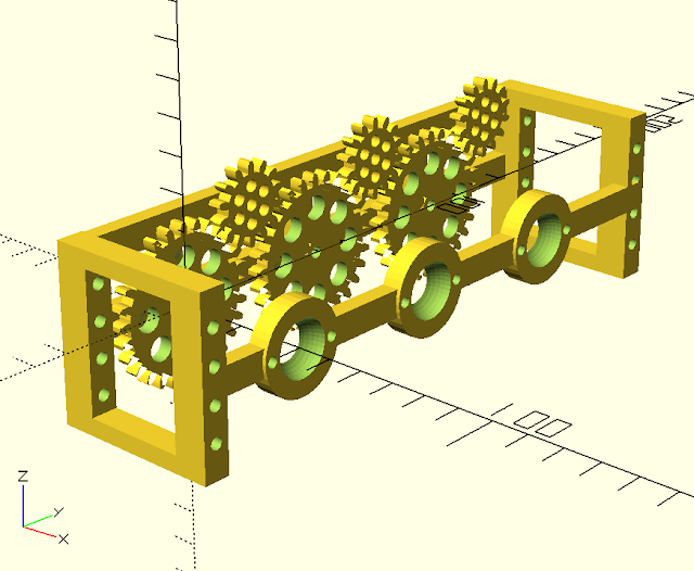
Centipede Robot V4 - Frame and Gears

I really liked the Hexagonal design of the previous version. Making the CAD files for that design was a lot of enjoyment.  However, that design was just not practical. It required too much printing, and ultimately did not solve any issues that could be designed away. The coverings prevented the ability to fix the leg-lever without taking it apart. So, at this part in the design process it needed to be simplified.

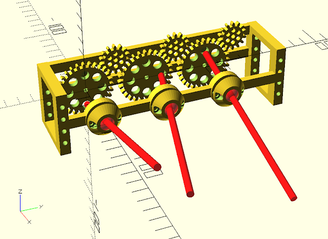
The new Design re-uses the ball-Socket universal joint from the previous version. It creates a frame, that will have a train of gears on it.  With proper use of variables for the distance and separation between the gears, it was possible to make this design parameter driven. I could create a 3 or 4 leg frame or any number.  In fact, I started with 4 legs, and for just the Proof-of-Concept, I reduced it down to 3.


I was able to quickly print out the new design.  I was able to re use the chopsticks as well as the ball and socket parts.  I also had some 3D printed gears already in the works from the Tilt! and Gear-box projects. I am currently satisfied with using the 1.5 modulus for the Gear teeth to radius design. It is larger than 1.0 and much easier to print and start using.
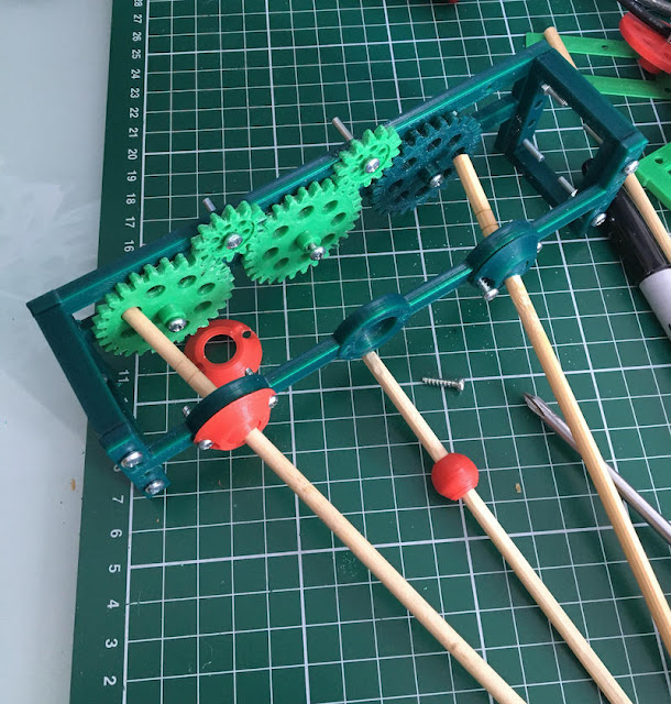
Assembly of the Prototype

Completed Prototype Test frame for Centipede Robot

Here is the proof of concept constructed and working. At the end, I use a gearbox to drive the prototype. The short video is on my YouTube channel.


Wow, ultimately it could look like this with 18 legs. This would be about 40 cm wide and 50+ cm long (without a head).  
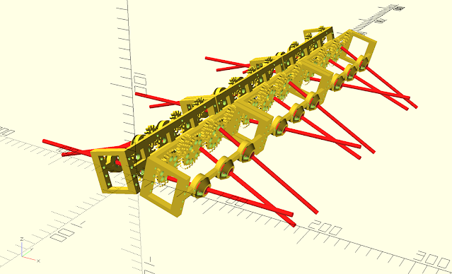
18 leg Centipede Robot


So this all seems possible, with a bit more printing and design work. I think for the full version, It would need to have a complete cycle on downlegs.

If you have more interest in what research is being done with Myriapod robotics. Here is a paper written by Yasemin Ozkan-Aydin while at Georgia Tech:  A systematic approach to creating terrain-capable hybrid soft/hard myriapod robots  While their approach is to build small single actuated legs, I am attempting to use recycled motors with minimal actuation. My approach is considerably more challenging (needless constraints?). I feel that the research in there paper will have faster and more interesting results.


Monday, April 22, 2019

Centi (#5) - New Leg Design is Printed

Centipede!!

Here is the latest print and video of the Centipede Project.


moving from OpenSCAD to print went fairly smoothly.  As you can see, I have enclosed the main rotating mechanism that moves the chopstick legs.  In this design in OpenSCAD, I have rotated everything along the Z axis, to make it easier to keep centered. The covering socket cap and ball all align, as well as the cam. You can also see holes along the structure, so that small screws can be used to assemble the leg segment. I am reusing screws from recycled printers that are used to bind plastic parts together.

OpenSCAD design
At the 'base' of the leg, I have created a hexagon. This seems to me to be 'self-bio-inspired'. I have not used hexagons in previous designs, so it is novel to me. More importantly, it fits the nature of the leg, as there is no specific 'down' or 'up.  One the walls of the cam base, I have added two small holes for M3 bolts. This allows me to connect two or more legs in sequence... thus forming the multiple legs of the Centipede.

New Print
At this time there are only two leg segments connected.  The M3 bolts are not visible, as they are inside the cam housing.  Note: I had a near-fail as I forgot to leave clearance between the cam housing wall and the bearing mount.  There are many issues to design out when doing project like this. This is why physically making the prototypes is very important to realize assembly issues.

New Gears to connect to Drive
At the base of the Cam Housing are two gears attached to the cam itself. The cam shaft runs through a bearing and then is connected to the gears.  The gears are "kegelrad" from the OpenSCAD library "Getriebe Bilbiothek für OpenSCAD".  The kegelrad could give me an ability to mount the drive gears at an angle different from the cam housing.  We shall see!  ;)

Saturday, April 13, 2019

Centi (#4) - Design Video

Centipede!

I have published a video of the initial design and 3D Printed "drafts" of the Centipede leg mechanism.  You can find the video below on my YouTube channel.


From a design perspective, the drafts have served their purpose. It is now a good time to take what we have learned and start a new draft.  

I like the concept of making each leg of the Centipede to be a "module" that can be replicated and connected together.  I am also realizing that I don't care much for the 'rectangular' frame that was in the drafts.  The legs may need to be moved around.  Honestly, the rectangles do not seem to match the aesthetic of an bio-inspired robot.

Here is my new concept that I am working on ...

Centi - a new aesthetic! - CAD in OpenSCAD

Saturday, March 9, 2019

Centi (#3) - The next iteration of design

Centipede!
The bio-inspired multi-leg walking robot!

It seemed that the main sprocket is capable of turning the chopstick legs, and the ball & socket were going to work.  This is the working theory, i will not be able to test a load on them until much later in the development.

The next iteration of the design of the motion mechanism was to start to incorporate a gear into the drive in order to turn the sprocket.  I did a number of changes in the CAD design.  I increased the size of the frame (height) and added M3 holes on the sides.  I updated the socket top to take recycled torx screws from a printer. 

Centipede next iteration of design

For the main design, I have added a 22x7mm skateboard bearing (red) to take the load of the leg (also red) and provide rotation. I extended the cam shaft to hold a gear.  Most important, I designed two gears, one to turn the sprocket, and the other to drive that cam gear.


Close up

The new print has noted improvements. Also, a number of issues that will have to be tweaked in the next iteration

Full View, new iteration on the left, original prototype on the right. 
 Together, the assembly will start to look like 1/3 of the walking mechanism.


Sunday, March 3, 2019

Centi (#2) - A Bio-Inspired Centipede Robot

Centipede!


a little more drafting of ideas around the mechanism.  

Draft of the first test
I drafted out a simple test mechanism to see how well the ball rotating in the ball mount would work with the circular motion of a wheel.  Also, the end of the leg would have to fit inside this wheel as well.

Print of the "minimal viable test"

building the Wild Weasel helped me understand how the bearing and gears could be used to transmit the mechanical energy and absorb the weight of the robot.  I think I will mount the main "sprocket" with a bearing.  After all, the weight of the robot will be directly on this wheel. 

In addition, I will need to add some teeth to the sprocket so that it can be turned with a motor. Finally, it is not too soon to start thinking about how this could be made into a modular component where it can be attached to other legs in the Centipede!

Monday, December 17, 2018

Centi (#1) - A Bio-Inspired Centipede Robot

Centipede!

I have always wanted to build a Centipede type robot.  It would combine a walking and turning mechanism. And be able to scurry around through obstacles and dreams. Now that I am a self-styled robotist with a 3D printer, I can build one!

DESIGN

Basically, the robot needs to support its weight and payload, be able to move forward/backward, and then steer to the left/right. The target motive force is a single/duo of dc brushed motors, with connectors between the 'segments'. It needs to carry a camera, lights, speakers, for streaming. It needs controller, wifi, RPI(?), and battery / portable power. 

Right now, I am satisfied with it "scurrying" about. But, getting those legs tangled in vertical things will be a future problem. I am not going to worry about that in the first prototypes.

The key to this design will be how to create the basic rotational motion of the leg to Lift-Place-Move each of the legs.  First thoughts had a pair of rotational gears, one to lift the legs, the other to move forward-backward.

Initial thoughts for Leg Motion, placement, and mechanisms
I created a couple of drafts on the cam/lifter/crankshaft thoughts.  But, this seems to be overly complex.  It needed simplicity.

Ball and Socket

The simplest thought would be to have a gear/cam spinning and moving a lever arm of the leg, that is suspended by a ball and socket arrangement. The most immediate concern would be the amount of friction in the ball/socket. This could be managed with some grease. future designs could even use metal or teflon to reduce the friction.  To the CAD!

First draft of the ball/socket - OpenSCAD
The plan is to 3D print a single full leg segment for testing and Prototyping. I am using a 'chopstick' for the leg.

First print for the prototype - Test, Adjust, and Print again!
The first rough print yielded some immediate feedback. The socket will need to be wider to better contain the ball.  but, sizing on ball for a chopstick style let was right.  I was playing wth an old cam print for sizing, this will go next into the design.  I am also thinking that having a modular/adjustable leg segment will be important.  But, I do not want to get too far ahead in the design there are still a lot of moving variables.

Internet inspiration:
Festo BioFinWave


here are some companies doing somethings with various linkages, but provide a 'fin' that can move on fluid surfaces:


It will be along way for me to go, compared to these systems.