Showing posts with label Gears. Show all posts

Sunday, August 11, 2024

Mojo5: The End of a Journey (#12)


Every project reaches that pivotal moment when progress halts, and the creative spark seems to fade. For Mojo5, that moment has arrived. This little robot has encountered a significant challenge in the design of its abductors. The servos have developed excessive backlash, compromising its ability to stand and walk effectively.

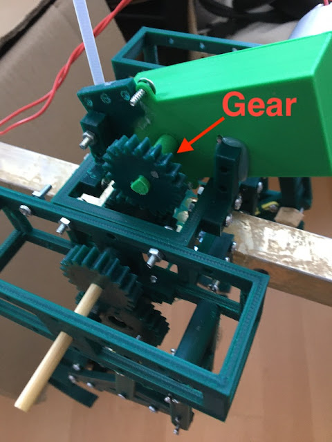
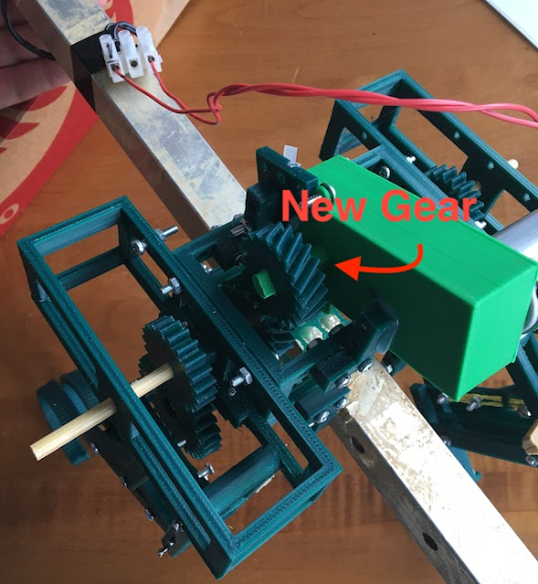
In an attempt to resolve the issue, I removed the servos and installed a 'static' gear to lock them in place. Unfortunately, this fix didn't fully eliminate the backlash, and the problem persists. Addressing this issue would require a major redesign, far more extensive than initially anticipated.

With a heavy heart, I’ve decided that it’s time to retire Mojo5. But as with all endings, this marks the beginning of something new. Long live Mojo6.

Sunday, November 13, 2022

Robot Runner (#5) - The Difference a Gear Type makes!


After the first prototype testing, it was evident that the 'drive gear' was slipping. This is the gear that is directly connected to the 3D printed gearbox. The gearbox itself may have some backlash (flex), but otherwise the system was pretty tight. It was just that the pressure from the leg mechanism was causing the gear to slip.

Here is a short video of the slippage


The fix to this turned out to be a simple change from a regular spur gear, to a helical gear. (the gear with a slant)

here is the original gear on the gearbox:

robot-runner with original spur gear


and the new CAD model (OpenSCAD)


This gear design has additional surface area touching in the teeth of the gear.  This is all that was needed to improve the operations.

Helical gears are one type of cylindrical gears with slanted tooth trace. Compared to spur gears, they have the larger contact ratio and excel in quietness and less vibration and able to transmit large force. A pair of helical gears has the same helix angle but the helix hand is opposite.  (hkgears.net)

New gear:

robot-runner with helical drive gear


Second prototype test:  Much better


All and all, I will pause this development for the moment. The mechanism is not performing as well as I would hoped for this point in time. I may return to the design. But, for the time, I am thinking more about a more functional base robot - back to MinOne.

Saturday, September 17, 2022

Robot Runner (#2) - skinny leg gets thicker

The skinny protype leg needs to be wider to support the robot. In general in needs to be more robust and handle the sideways transitional forces. To do this I am making the leg as wide as the 'pin' in my previously designed hinges. This pin is a 40mm finishing nail, which I have a box of. I have used them has hinge pins in the design of the wild weasel and Mojo4.  This will provide some of the support needed for the sideways forces. The design must be carried forward down to the lower leg and foot.

Robot Running Leg Mechanism -v2

As the width of the robot increases, it is not possible to determine on which side the compliant link will go and the placement of the crank and crank gear. The back lifting linkage, does not need to be 'wide' as it is only projecting the motion, not the support.

Robot Running Leg Mechanism CAD (pins not shown)

Also in this step, I am starting to think of how to drive the crank gear with a motor.  I have a 3D printed gear box from a previous design to reuse (Tilt! and 3D gearbox).  This gearbox will allow the robot to be driven by a brushed motor from a recycled printer.

Here is a video of the current design step:


As you can see, there is a lot of movement generated by the motor. The leg is thrown around creating an oscillation and some unwanted impulse movement.  This will need to be considered (dampened)in future design steps.

Sunday, November 21, 2021

Mojo3 - A Robotic Dog (#11) - Wrapping up the Design

Mojo 3 has been a good learning experience, but for now i will shortly be moving to a 5 bar design and more complete robot concepts.

Here is the latest video:


Summary

I really like the small compact design of Mojo3. The prototype fit nicely on my desk. It is easy to assemble and did not take long to print on the 3D Printer.  I intentionally made it smaller than Mojo2 in order to get it to work with small 9g servos.

Also in this design, the weight of the robot was carried from the legs directly to the chassis through a 8mm (skateboard) bearing. This is a significant improvement over Mojo2.

Finally, I took the 'compliance' part of the robot out of the design. These legs are driven strictly by the servos, and gears attached directly to the servos.  This approach has the advantage of providing the most direct torque to the leg components. 

Unfortunately the Knee arrangement with a gear and type of pinon/cam, does not work.  It was easy to calibrate. You could just lift the arching gear teeth and put them in the right locations.  However, once the robot was under load, it was prone to slip.  The video shows this very clearly.

Going Forward

I have started a 5 bar leg design.  This arrangement should be easier to get a full range of motion. The next design will incorporate Inverse Kinematics. I will try to write some meaningful blog entry on that.

Saturday, October 30, 2021

Centi (#6) - Playing with the Design


Perhaps it is time for some new perspective after a pause of 2 years.  For a "Weekend Project", I decided to re-examine the Centipede design that I had started before.  At this time, I have a bit more experience with gears and how to make the daisy-chain of gears that would be necessary for this type of robot.  I wanted to verify, with a physical test, how such a mechanism could fit together and if the gear train would have enough torque for it to actually move the robot.  For this test, I have learned much more about the potential, and as well as some limitations.

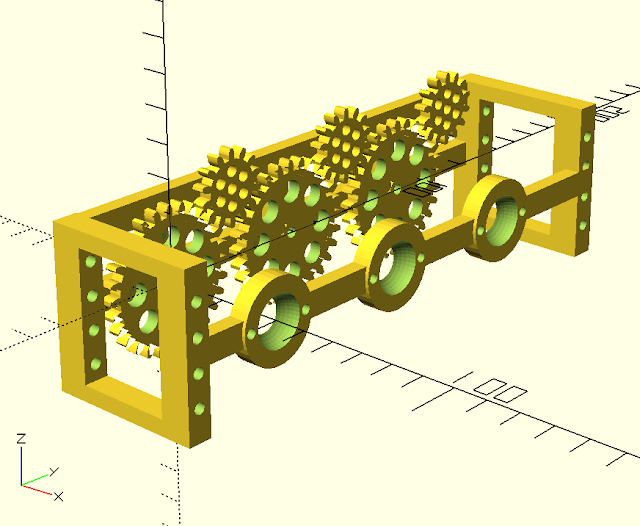
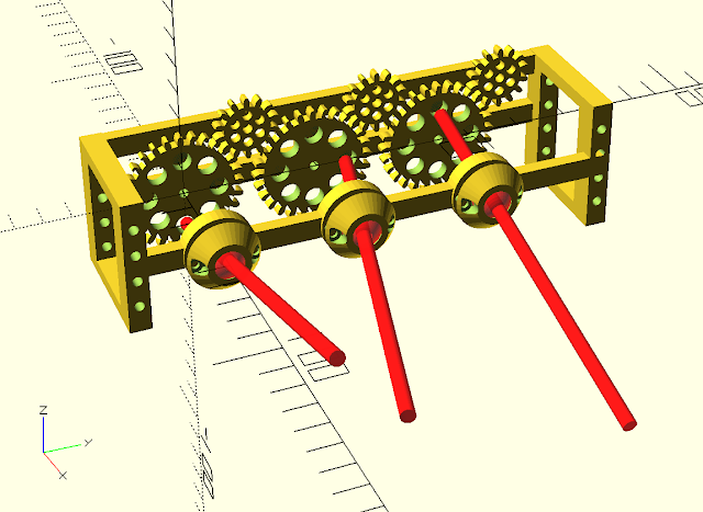
Centipede Robot V4 - Frame and Gears

I really liked the Hexagonal design of the previous version. Making the CAD files for that design was a lot of enjoyment.  However, that design was just not practical. It required too much printing, and ultimately did not solve any issues that could be designed away. The coverings prevented the ability to fix the leg-lever without taking it apart. So, at this part in the design process it needed to be simplified.

The new Design re-uses the ball-Socket universal joint from the previous version. It creates a frame, that will have a train of gears on it.  With proper use of variables for the distance and separation between the gears, it was possible to make this design parameter driven. I could create a 3 or 4 leg frame or any number.  In fact, I started with 4 legs, and for just the Proof-of-Concept, I reduced it down to 3.


I was able to quickly print out the new design.  I was able to re use the chopsticks as well as the ball and socket parts.  I also had some 3D printed gears already in the works from the Tilt! and Gear-box projects. I am currently satisfied with using the 1.5 modulus for the Gear teeth to radius design. It is larger than 1.0 and much easier to print and start using.

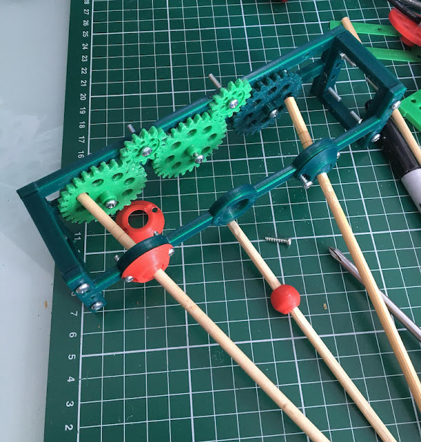
Assembly of the Prototype

Completed Prototype Test frame for Centipede Robot

Here is the proof of concept constructed and working. At the end, I use a gearbox to drive the prototype. The short video is on my YouTube channel.


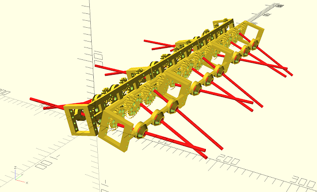
Wow, ultimately it could look like this with 18 legs. This would be about 40 cm wide and 50+ cm long (without a head).  

18 leg Centipede Robot


So this all seems possible, with a bit more printing and design work. I think for the full version, It would need to have a complete cycle on downlegs.

If you have more interest in what research is being done with Myriapod robotics. Here is a paper written by Yasemin Ozkan-Aydin while at Georgia Tech:  A systematic approach to creating terrain-capable hybrid soft/hard myriapod robots  While their approach is to build small single actuated legs, I am attempting to use recycled motors with minimal actuation. My approach is considerably more challenging (needless constraints?). I feel that the research in there paper will have faster and more interesting results.


Friday, August 13, 2021

Gearboxes for Recycled Printer Motors (video)

 For those interested in making Gearboxes for Recycled Printer motors.  I have posted a video on my YouTube Channel that shows the asseymbly of the gearbox. Unfortunatly, it is not an instructional video, but it does show how to build it.


Monday, August 9, 2021

Tilt! - A Self Balancing Robot (#8) - New Gearbox for Motor and Wheels


A new gearbox for the self balancing robot.

The reuse of the pulley system is not working on the robot. Therefore, I started the whole gearbox design for recycled printer motors.  Now that there is a somewhat functional gearbox, it is time to return to Tilt! and see how the gearbox can be applied.

Here are the parts!  Now, just Engineer a new Motor mount and Wheel assembly!  


Engineer That!

New Motor Gearboxes layout with the old mounting brackets

Rough draft started - the concept of the new mounting system will be similar to the previous design iteration. Now, instead of using pulleys on a wheel with an axel, the axel will be directly part of the output shaft of the gearbox.  There will be a single 22mm bearing to take the load/weight of the robot instead of transmitting that to the gearbox/motor.

New Motor mount and gearbox

The New motor mount is wider than the original chassis and will fit 'around' the existing battery box. This frame will take use of the 1cm holes to allow for easy modular construction.  The gearbox, has new brackets so that it can be screwed to the new mount.  The old wheels are reusable, I will have a friction dependent plug that sets in the hub of the wheel and securely fits the output shaft of the gearbox.

Tilt with new 3D printed Gearbox - more Torque, less speed

NEXT:  Look for the new video showing the assembly of the gearbox. This is not a full instructional video, but does show how a simple gearbox can be 3D printed to allow for the use of recycled printer motors in robot construction.

Sunday, July 11, 2021

Gearboxes for Recycled Printer Motors (#2)

The final prototype build of the 3D printed gearbox for using recycled printer motors.  To see the initial development, see Part 1.


Gears
First version of Gear Design (above) vs. Current version (below)

Here are the versions changes from my initial gear design to the current one used.  The latest version has fewer teeth and is slightly wider on the smaller in-set gear.  This has required the housing box to be increased in size.  I used this extra design cycle to increase the distance between the axles in addition.

First version (right) vs. Current version (left) - output gear/shaft missing from picture


The Assembled Gearbox
unfortunately, you can not see the internal gears, because of the inclosing housing.  This design is working.  It seems to be good tork on the output shaft. The rotational speed is significantly less (~6:1) than the motor speed.  Even better, it will run without getting jammed. 

The next steps will be to design in a method for securing the gearbox to the robot. This may be dependent on the robot it is being applied to. The gearbox increases the space required for the motors.  My robots tend to be small, so this will have significant impact.

In addition, I would like to remove the load from the output shaft using 8mm skateboard bearings.  Finally, the drive shaft will need to be adjusted to provide a better attachment method for the output. 

Recycled Printer Motor 3D Printed Gearbox - First Complete Prototype Build


Robot Application
Since 3D printed gearboxes are not the focus of my robot building, this initial disign is good enough for now to move forward.

The Milli Robot will be fitted with the new gearbox. The connection between the motor and the helix shaft has been problematic. The rotational rate was too fast. Frequent jamming (due to a broken stabilizer) resulted in the drive shaft burning out the drive gear. A gearbox and new stabilizer should get the robot development back on track.

Broken-bot Millipead Robot with the WildWormDrive
The motor to Drive section will be re-designed with the 3D Printed Gearbox


Tilt!  A self-balancing robot will also be fitted with the new gearboxes. The original concept to use recycled motors, used the belts from the printers. The belt system is functional, but the fast movements required to provide balance created slippage in the belt. Typically slippage can be reduced or removed with a tensioner. However, I think in this caseitwoudl be best just to replace the belts with a gearbox system.  The drive mechanism is not the focus of this robot, therefore simpler is better.


Tilt! Robot - will be redesigned using the 3D Printed gearbox
The pulley-belt system had too much slippage

Sunday, April 11, 2021

Gearboxes for Recycled Printer Motors (1)


Typical brushed DC Motors salvaged from old printers
part 1

I love to recycle old electronics and printers for parts. I find taking old printers apart is a fascinating way to learn the mechanics of robots. I now have a nice collection of small 9v, 12v, and 18v brushed DC Motors. This is the basic mechanical part of robots! However, using these motors has proven to be difficult as they often have a high rotation speed and low torque. For robot projects, you typically need the opposite, slower rotation, and high torque.  The only way to achieve this is to use a gearbox with the motors. Gearboxes use the mechanical properties of gear-reduction to reduce the rotational rate and increase the torque.

Now it is the time in my robot development to build an accessible gearbox that will work with my projects and recycled motors.

I have worked with gear reduction on a few projects.  notably the tank track and wild weasel drive. Discussions about Planetary gears.  More recently with Tilt!, using the motors with a belt.

Here is a nice Instructable that i am using for inspiration, "3d Printed Gearbox for Small Dc Motors". It does not mention much on the actual design/engineering of the gearbox.  But, it is a nice video and a good place to start.  There are plenty of other YouTube videos that also show the capability of 3D printing gear boxes. Remember, it is far too easy to spend (waiste?) time watching others make videos, then just doing it yourself.  ;)

Starting from the Beginning

What do I need?  (Functional Requirements):

  • must work with recycled printer motors 
    • brushed 9-12V motors 
    • bare metal spindle
  • 16:1 or better reduction and torque
  • minimal backlash (movement in the output shaft)
  • keep the dimensions to less than 1.5 to 2 size of the motor

softer, but important requirements:

  • something easy to print, use, and maintain
  • reliable, not prone to jamming
  • No stripping of the motor gear interface

The concept:

the motor spins a series of gears, each time a small gear with ess teeth drives a larger gear with more teeth. each stage reduces the rotational rate of the gear that is being driven. There needs to be 4-5 of theses connections. finally it is connected to an output shaft. This is all contained on just 2-3 axels, contained in a box, and bathed in grease.

Let's start with a basic gear:

I am using OpenSCAD for my designs.  For gears I highly recommend the Getriebe.scad library from Dr Jörg Janssen, he rocks!  It is written in german, but hey? what's wrong with that? ;)

The primary gear will have a large and small gear physically connected. I am starting with 14 and 28 teeth (a ratio of 2) with a modulus of 1.0 (relation between teeth and diameter). I will also use a angle on the teeth on the gear, to help reduce the gears from raising up on their axles when spun at high speed.

Gear v1

Stacking the next gear:

so the big design question, is what is the separation of the gears? this should be the diameter of the large gear minus half the diameter of the small gear plus some tolerance. Now a good engineer will be able to calculate the tolerance needed based on the 'pressure faces' of the gear teeth.  however, I am not that engineer today and my 3D printing lacks some precision, therefore I am going to start with 0.5mm. ;) 

Stacking the next gear in place

Full gear stack:

Next, add the 3rd primary gear to the top of the first axel. 

For the motor gear (Red), I am using the same gear configuration as the small gear, but making it 1.5 taller than the standard gear height.  

For the output shaft gear (Green), I am using the same gear configuration of the large gear, but will add a shaft on top of it. For this first build a version, i will just print the shaft as part of the gear. However, this is not good design. The shaft should not be printed, ideally it will be a different material, preferably metal. In fact, this is the weakest part of this design so far. Load bearings should be added to this shaft to absorb the load of the shaft and translate it to the box (or any other non-moving part of the assembly). For now, I will print - it is fast and this is more of a "pathfinder" exercise.

Full gear stack

The Box

The gears will be placed inside a box. It will be important to keep the gear from getting foreign matter jammed in the gears. Also, the gears will need some lubricant grease, which will be messy. Most important, the box will provide the structural strength needed to hold the gear axels in place. On one side the motor will be attached. On the other side will be the output shaft and associated load (a bearing would be ideal, next version).  In addition, I will add some mounting holes, so that I can bolt the gearbox to my robot creations.

My first design thoughts are to have the motor and the gears attached to a plate that can be screwed on to the box. The rest of the box will be just the compartment, output shaft hole, and mounting support. This part of the box can be printed 'upside down' (see diagram).

"top view" (no top plate) to make sure all the gears fit

The CAD view, can be used to visually determine if there will be issues with the screw placements.  In this next view you can see the motor (in blue) will over lap the screw positions for the motor plate, as a result, I think i will lengthen this side of the box to compensate. (I also have an issue with the wall placement on the right side)

Use the CAD views to verify the design

Full Design

drafting out the box and all of the screw holes, will complete the initial design.  Now it is time to review the CAD drawing, look for flaws (like forgetting the primary axel holder in the output_shaft_plate). After some adjustments it looks like this:

First full design

Time to start 3D printing and testing

The first results - work, but leave a little to be desired. I assembled the motor, gear, and the three primary gears together. I used nails as a quick axel. Hooking up about 8V of power, it gave it a quick spin. It does work! This test was outside of normal operating conditions as it will be enclosed in a box and axles will be supported on both ends.  The operations were a little rough (no grease!). Therefore I did not post of video of it.  Here are some pictures.


Gearbox version1, first print

Gearbox version1, top view

Next Steps

For the next steps on this project, I will be making adjustments and some improvements. Primarily I will reduce the number of teeth, and increase the modulus. This should result in a similar sized output, but with less teeth. I believe the lower number of teeth will print easier on my 3D printer. I may also add a few mm to the size gears as well. Check back to see on the next post.

Thursday, June 25, 2020

Intergalactic Planetary (gears)!

Just doing some thinking and sketching on how best to use Recycled Printer Motors in my robots. 

One of the Totally Not Evil Robot Army motivations, is to make robotic creations by recycling parts from existing technology. To RE-USE, is the best approach to waste management. -- and also of course, because I am really, really cheap.  ;)

Recycled Printer Motors

Most computer printers have these nice (DC Brushed) Motors, but they tend to be too fast and with out a lot of usable torque for my projects. This would be expected, since the printers they come from have a lot of built in gear reduction.  For power, they typically require 12-18v. These are not light either, they have some weight to them. In order to utilize these printer motors, they will need a gearbox to both reduce speed and increase the torque - which is exactly what gearboxes do for motors.

The Planetary Gear is a good choice for a compact way of converting the motors output into a stronger more useful force.

The Planetary Gear is made up of 4 pieces, The Sun Gear, one or more Planet Gears, The Carrier (connecting Planet gears) and on the outside, the Ring.

Named Parts of a Planetary Gear Box

The configuration of a planetary gear box can vary based on specific needs. Any one part of the system can be 'fixed' which allows for the other two parts to become the Driver (input) and the Output.  

Example:  by fixing the Ring and attaching the drive motor to the Sun, it makes the Planetary Carrier to become the Output and move.  Likewise, you could fix the Carrier and attaching the drive motor to the Sun Gear, would cause the Ring to be the output and move.

Here is a quick 3D print or sketch of the Planetary "Wheel".  Here the motor and Carrier are the same part. This allows the motor to directly drive (input) the Sun gear.  Since the planets are fixed, the Ring will move. I have built the Ring gear to be the inside of a wheel.


Planetary Wheel
Motor Mounted on the Planetary Carrier

On the reverse side you can see the planetary gears encased in the wheel. The Sun Gear is removed.


Complete "Planetary Wheel"


Gear Reduction with Planetary Gears


The actual gear reduction and torque increase can be calculated based on the number of teeth in the gears or the radius of the gears (given a specific modulus).  The equations are similar to basic gear equations, however there are differences due to the planetary gear set.  here they are:

For the gear ratio of a basic gear 

    i = Z2 / Z1 

where Z are the number of teeth on Gear 1 and Gear 2

For the Planetary Gear, we have the number of teeth - Zs for Sun Gear and Zr for the Ring. The number of teeth on the carrier does not matter, since it is derived and removed from the equations. (also, it does not matter how many actual planet gears you have).

the equation for planetary gear reduction is:

    i = 1 + (Zr / Zs)

Here is a nice little summary video of deriving the gear-ratios of Planetary Gears.


(Update:  here is a nice summary sheet from the MIT FAB LAB)

Testing the 3D printed gear box


I was able to make this wheel work pretty much out of the print.  I did have some difficulty in the motor shaft 'stripping out' the inside of the sun gear if the gears were blocked.  this is the same problem encountered on the Milli project.  I believe some glue may help hold the gear in place, but this does not seem to be a sustainable solution. I would have difficulty replacing the gear when needed.

As a result, The Sun gear would slowly lift off of the motor spindle when operated at full speed.  (A failure you would not want if the Wheel was part of an inter-planetary rover.)

Looking forward, at these brushless motors, I believe a belt and tensioner system may work best. Most of the motors I have, already have a nylon belt gear on the motor spindle.  I will try to use this combination in one of my next projects.


Postscript

Hi all, this post was somewhat delayed due to some personal health issues.  I am doing much better now, thanks!  I have some upcoming work on a balancing robot - using Printer Motors that I am currently considering.  More to Come!  Thanks! Doug

Thursday, April 9, 2020

Milli (#8) - Rethinking the Motor and Spendel

Milli is a bio-inspired robot that uses a single actuator to create standing wave motion.


Where to go next on the design of the WildWorm drive and Milli??

As expected, the recycled printer motor that I am using (9-12v) powered by a 18v rechargeable drill battery, is too much for the little robot. (duh!)  When testing, the rotational speed of the motor is too much for the directly driven helix spindle.  After some testing this has lead to the helix base to be burnt out by the motor spendel.

Milli's WildWorm drive - burnt out helix mount separated from the motor.

What is needed is a gear reduction, to reduce the rotational speed, and increase the torque of the helix.  This is very similar to the gear reduction used for the same motors on the Wild Weasel track.  Here you can see the video of the gear reduction built into the track:


But Where to put this on the rather simple chassis of Milli?


Milli - Motor Mount

Actually, there is plenty of room.  With the next iteration of design, I will:

  • Add a bearing to the chassis, creating the mount for the helix.  this should reduce any load from the wildworm drive on the motor itself.
  • A shaft will connect the helix, through the bearing to a similar sized 3D printed gear.
  • The Gear train will consist of a small gear directly on the motor.  This will drive a large gear with coaxial small gear. this small gear will drive the helix gear.  (A quick estimate would have 18mm diameter to 40mm diameter gears. times 2 ~ 4.8:1 gear ratio)
  • If another gear set is needed, it can be added relatively easily.

Milli - Chassis with Recycled Printer Motor

Unfortunately, this is all conceptual at the moment.  It is not even in the CAD system just yet.  However - the thoughts have given me some new insight on Mojo3 - and there will be a new design blog post out shortly.


Stay Healthy!

Saturday, February 9, 2019

Wild Weasel - tracked robot (#1)

I have an interest in building and designing out a tracked robot... for some reason. :)  

Tracked robots have static stability, and typically should not get 'stuck' on terrain the way wheeled robots do. Also, you can build, drive, and steer a tracked robot with only 2 motors. The downside of the design is that to turn, they have to 'skid' or slide.

I wanted to design a track system that will be modular and can be combined with other tracks and platforms to easily create new robots. I really like the modular designs of the Intukun pipe inspectors robots. Their mini-track crawler is an impressive piece of crawling hardware. Of course, I wanted to build one like this too.
MiniTrac (80mm x 100mm x 400mm) - by Intukun

The other design influence was closer to the Maker space. On Thingiverse, I found a great design of a robot tank by Tim Clark, 
MR6 - Mini Prototyping Tank Robot. Tim had obviously put a lot of thought into this design. This robot is at least his third design variant on crawling robots. Being his latest model, it probably has the most learnings. 

I really liked the skateboard bearings he is using, as well as the track design, and the various layers of support frame. Although, I am still not sure what is the advantage of raised cog/sprocket to form a triangle.  I did not use his design, except for influence - I needed to have the design in OpenSCAD, and he did not provide source files openly.
MR6 - by Tim Clark


I set out to design my own tracked crawling robot using ideas from both of these designs. In addition, I wanted to re-use 12V motors that I have harvested from old printers.


Track, Sprocket, and Motors -- Ready for Design!

Design Concepts


I want the motor to be inside of the treads, so that there is no axel crossing between a motor and the gears, thus raising the ground height of the robot frame.  Only the motor power wires and the mounting frame will need to go on to the track module.  Thus the height dimension of the unit will be dependent on the motor size and clearance of the treads and sprockets.


(Red) Motor between two sprockets, creating a contained track modual.

the width of the treads has to account for the width of the motor. This affects the width of the sprocket/cog.  The sprocket will contain a 22x7mm skateboard bearing.  So, ultimately the sprocket is dependent on the bearing size, and the tread is dependent on the sprocket.


Frame to hold the motor and sprockets

The length of the track would be dependent on the sprocket size, motor size, and amount of gear reduction needed between the motor and the drive sprocket.  This value had to be determined in a few design iterations. Also at play the size of the gears and the size of the sprocket are closely coupled. In my build process I needed to add size to the sprocket to account for the larger gears I needed.

Frame and Gears to drive the treads

The sprocket size was increased, to provide more clearance to the motor and gears. Since the sprocket gear tooth size is directly linked to the tread size, increasing the sprocket, but keeping the tooth size, meant that I needed an additional tooth on the sprocket.  Thus in a design iteration, changed the sprocket from 12 teeth to 13 teeth.  This very subtil change has impact on the rotational angle location on the sprocket disc. 

Size of the sprocket determine number of teeth in Sprocket and Tread size

Tread design

I examined Tim Clark's treads very closely. I also examined the changes he made from earlier designs to later ones. The result I saw was from early to later designed the length (size of step) of each tread was getting smaller and smaller.  This result in a more fluid chain of treads.


Wild Weasel - Tread Segment
To keep the build process simple, I am using small nails that slide through the Tread Segments to lock them together.

Gear Design

The gears used to transfer the torque from the 12v printer motors to the sprockets had to be carefully designed and fitted.  The motor has a high speed and needed to be stepped down in a compact space.
I experimented with gears reused from old printers.  the common design is a large top gear connected to a smaller gear on the same axis.  This provides a method to reduce the rotation speed for each gear step.
The motors had diagonal toothed gears already on them.  I used a open source gear library in OpenSCAD to design the gears.  Using more fine settings on the 3D Printer produced incredible results.

OpenSCAD library by Dr Jörg Janssen, Getriebe.scad.  I highly recommend this library, although it is in German. (don't let that scare you! ;)
One gear of 4 used in the design.

Final Design


Interestingly, building laterally symmetrical (no upside, downside) means you do not need to have a left or right side. the unit can be flipped or rotated to either side of the robot. By making two copies, I can rotate one tread around to have the symmetrical pair, without having to have a second design.


Track Modual

Here is assembly construction of the first robot.
Wild Weasel tracked Robot Chassis - OpenSCAD
Here is the first print made of the robot, complete with parts.  Completely 3D printed.
Printed Design - Wild Weasel Tracks and Robot