Monday, November 8, 2021

Mojo4 - 5bar design (#1)

Time for A new Mojo Design!  Time to get back in to the wonderful world of Quadrupeds!

I am trying out a new design approach for a new Quadruped.  The 5-bar linkage.  

This approach has been successful in several quadruped designs found on the internet. (one of my favorite is by Oracid: video.) 

It has a full range of motion with only requiring only 2 servos per leg. in addition the leg linkages are supported by pin/hinges on the frame. This should reduce, but not eliminate the force exerted on the servo motors.

Linkages are just mechanical arrangements of bars/links/connectors and pivoting connections. Given different types of configurations, it is possible to get a wide range of applications. One of the most common linkage people have seen on old steam engines. Here, the steam exerts a linear force that is then converted to a rotational force to move the trains wheels.

For a 5 bar linkage, only two bars are connected to the servos. by changing the angle on just these two servos, one can get a wide range of motion.

By I.Elgamal - Own work, CC BY-SA 4.0

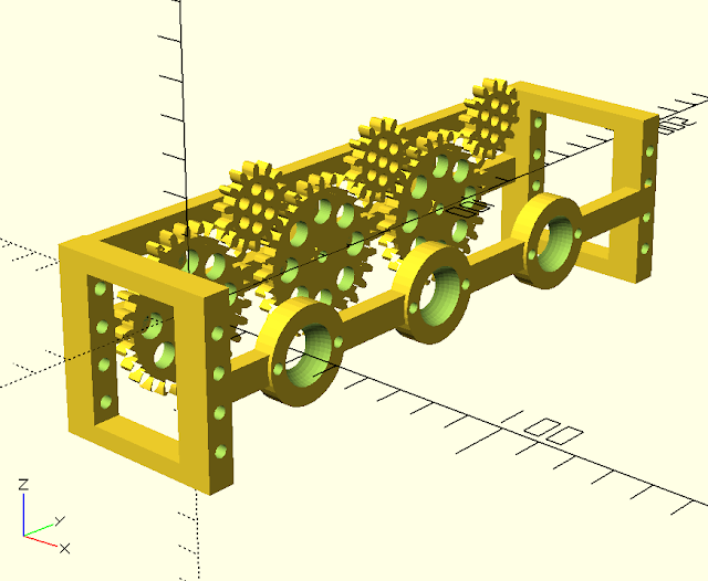
For my design, I will be connecting the top two pivot points together to create a 'diamond' of the linkages.  next, at the bottom, the bar is extended further out. Here is where the 'paw' will be connected.

5 Bar Linkage in a diamond with 'paw' configuration

I am hoping that this arrangement of parts should provide significantly more vertical lift in the leg. Mojo2 did not have significant lift and often shuffled.  Also, Mojo3 had more left control, but the servos were overpowered. This combination should provide both the needed strength and lift required.

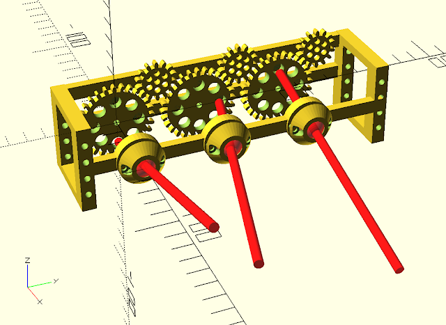
To control the leg, the two servos will be connected in smaller 4 bar connection to the sides of the Diamond. The key in the design is to keep the servo horns parallel to the bars that they control. In operations, the servos themselves act virtually identical to the top diamonds sides.

Mojo4 Robot Leg design with control actuators

The linkage parts will be 3D printed (of course) and I will be using a small nail as the hinge.  This hinge arrangement is very similar to the track design I used on the Wild Weasel. (video)  Having a reliable design in the CAD and 3D printing makes building robots a lot easier. With this design I can remove a freshly printed part and assemble it with only basic smoothing and cleaning.


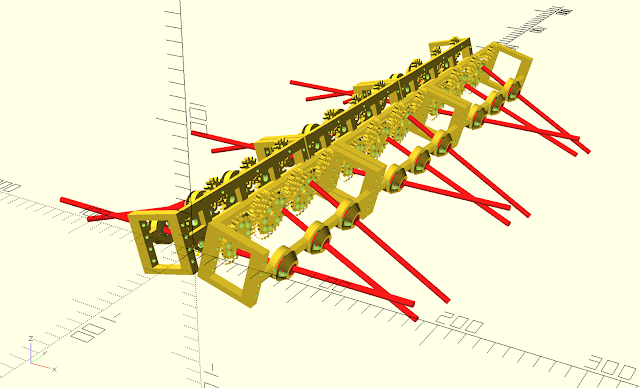
For my first rapid prototype testing, I will only have a test stand to validate the movement of the leg. I am re-using parts and the wiring from Mojo2.  I will reuse the Mojo2 servos, MG995 servos. These are 13kg servos. They are slightly heavy for this application at 65g.

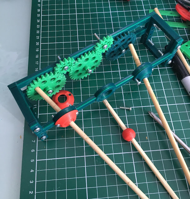
Here is what the constructed leg mechanism looks like:

Mojo4 Robot Test Leg

Next Steps:
Now that the basic structure is printed and built for the 'test stand'. I will work on the software to move the leg. For this robot, and the first for Mojo, I will implement some form of Inverse Kinematics. With Inverse Kinematics, it will be possible to instruct the leg the exact position it should talke, and the IK will determine the correct angles to command to the servos.

Saturday, October 30, 2021

Centi (#6) - Playing with the Design


Perhaps it is time for some new perspective after a pause of 2 years.  For a "Weekend Project", I decided to re-examine the Centipede design that I had started before.  At this time, I have a bit more experience with gears and how to make the daisy-chain of gears that would be necessary for this type of robot.  I wanted to verify, with a physical test, how such a mechanism could fit together and if the gear train would have enough torque for it to actually move the robot.  For this test, I have learned much more about the potential, and as well as some limitations.

Centipede Robot V4 - Frame and Gears

I really liked the Hexagonal design of the previous version. Making the CAD files for that design was a lot of enjoyment.  However, that design was just not practical. It required too much printing, and ultimately did not solve any issues that could be designed away. The coverings prevented the ability to fix the leg-lever without taking it apart. So, at this part in the design process it needed to be simplified.

The new Design re-uses the ball-Socket universal joint from the previous version. It creates a frame, that will have a train of gears on it.  With proper use of variables for the distance and separation between the gears, it was possible to make this design parameter driven. I could create a 3 or 4 leg frame or any number.  In fact, I started with 4 legs, and for just the Proof-of-Concept, I reduced it down to 3.


I was able to quickly print out the new design.  I was able to re use the chopsticks as well as the ball and socket parts.  I also had some 3D printed gears already in the works from the Tilt! and Gear-box projects. I am currently satisfied with using the 1.5 modulus for the Gear teeth to radius design. It is larger than 1.0 and much easier to print and start using.

Assembly of the Prototype

Completed Prototype Test frame for Centipede Robot

Here is the proof of concept constructed and working. At the end, I use a gearbox to drive the prototype. The short video is on my YouTube channel.


Wow, ultimately it could look like this with 18 legs. This would be about 40 cm wide and 50+ cm long (without a head).  

18 leg Centipede Robot


So this all seems possible, with a bit more printing and design work. I think for the full version, It would need to have a complete cycle on downlegs.

If you have more interest in what research is being done with Myriapod robotics. Here is a paper written by Yasemin Ozkan-Aydin while at Georgia Tech:  A systematic approach to creating terrain-capable hybrid soft/hard myriapod robots  While their approach is to build small single actuated legs, I am attempting to use recycled motors with minimal actuation. My approach is considerably more challenging (needless constraints?). I feel that the research in there paper will have faster and more interesting results.


Monday, September 6, 2021

Tilt! - A Self Balancing Robot (#9) - The Balancing Act


New Gearboxes are installed time to make the balancing happen. - with video!

Video


Ugh, I spent a whole session trying to figure out why the M6050 was not communicating with the I2C bus.  It was clearly visible but no connection.  It seems that the circuit would prefer to have 3.3V in the Vcc, I was sending 5V.  Switching to 3.3V solved the problem. On to the next stage.

here are the first results:

First Test default:

double Kp = 40; // First adjustment
double Kd = 1.1; // Second adjustment
double Ki = 0; // Third adjustment

This seemed to be working, but the reaction of the motors was a bit off.  Some quick searches of LMotorController motorController() didn't reveal too much.  But I do see a factor in the code for the left and right speed factor.  These were set to 0.6.  IF these are associated to tune down the PWM signal sent to the motors, then it could mean that it is under powering.  I moved these to .8 and got a much more robust effect on the motors. On to Tuning the PID

Second Set  Test  default:
double Kp = 50; // First adjustment
double Kd = 1.0; // Second adjustment
double Ki = 0; // Third adjustment

I am getting some oscillation now, the Kd starts to tune this down.  Clearly from the video the robot has a tendency to lean in one direction.  I adjust the frame by putting hot glue between the sections, just squeezing it in and letting it harden.  I also suspect that the battery (weight inside) may be shifting forward. Using some cork, have wedged it in to prevent momentive shifting.

Third Set  Test  default:

double Kp = 55; // First adjustment
double Kd = 1.0; // Second adjustment
double Ki = 0; // Third adjustment

This was the most aggressive on the Proportional control constant that I used in the First Session. Certainly a little more 'attack' on the balance change. Starting to get some stable oscillations. 

Forth Set  Test  default:

double Kp = 55; // First adjustment
double Kd = 1.0; // Second adjustment
double Ki = 10; // Third adjustment

With this change, I added the Ki - Integral constant in to the PID. The result of Integral is to help smooth out the oscillations. There is a negative effect of controller 'Wind-up' as the integral values do not dissipate quickly. However I do not think I experienced this in this session. 

Overall the new settings in this set were not as desirable as the previous settings. Stability, subjectively, was reduced. Also, it seemed that I had a 'short' or disconnect in the power - OR - the PID was overwhelmed and stopped for about 1/2 second. Tilt! just fell over, and then everything started back up. 

Weight Adjustment 

Finally, I added a moderately heavy weight to the top of the robot. I used a Transformer that I had salvaged out of speaker. The additional weight seemed to slow the 'jitter' of the oscillations. However, the motors were unable to overcome the falling weight when it was tilted.

It seems that the robot has a tilt that needs to be identified and removed.  This is also leading to instability.  perhaps it is associated with the 'level-ness' of the sensor.

And - after repeated testing the blue wheel started to fall off. This was a temporary solution to start with.  It seems the repeated jerking started to effect the friction connection that was holding it in place. 

Tilt! A Balancing Robot - 3D Printed, Recycled Motors

Next Steps

1) identify the source of the lean/tilt

2) attach some weight to the top

3) investigate using the 12V battery and 5V power source

4) investigate easy remote control solutions

Friday, August 13, 2021

Gearboxes for Recycled Printer Motors (video)

 For those interested in making Gearboxes for Recycled Printer motors.  I have posted a video on my YouTube Channel that shows the asseymbly of the gearbox. Unfortunatly, it is not an instructional video, but it does show how to build it.


Monday, August 9, 2021

Tilt! - A Self Balancing Robot (#8) - New Gearbox for Motor and Wheels


A new gearbox for the self balancing robot.

The reuse of the pulley system is not working on the robot. Therefore, I started the whole gearbox design for recycled printer motors.  Now that there is a somewhat functional gearbox, it is time to return to Tilt! and see how the gearbox can be applied.

Here are the parts!  Now, just Engineer a new Motor mount and Wheel assembly!  


Engineer That!

New Motor Gearboxes layout with the old mounting brackets

Rough draft started - the concept of the new mounting system will be similar to the previous design iteration. Now, instead of using pulleys on a wheel with an axel, the axel will be directly part of the output shaft of the gearbox.  There will be a single 22mm bearing to take the load/weight of the robot instead of transmitting that to the gearbox/motor.

New Motor mount and gearbox

The New motor mount is wider than the original chassis and will fit 'around' the existing battery box. This frame will take use of the 1cm holes to allow for easy modular construction.  The gearbox, has new brackets so that it can be screwed to the new mount.  The old wheels are reusable, I will have a friction dependent plug that sets in the hub of the wheel and securely fits the output shaft of the gearbox.

Tilt with new 3D printed Gearbox - more Torque, less speed

NEXT:  Look for the new video showing the assembly of the gearbox. This is not a full instructional video, but does show how a simple gearbox can be 3D printed to allow for the use of recycled printer motors in robot construction.